


75
Description of devices
3
SEQUENCE PROGRAMMING
3.9 Description of devices
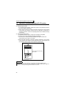
3.9.1 Device List
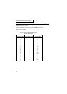
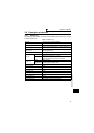
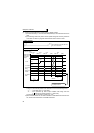
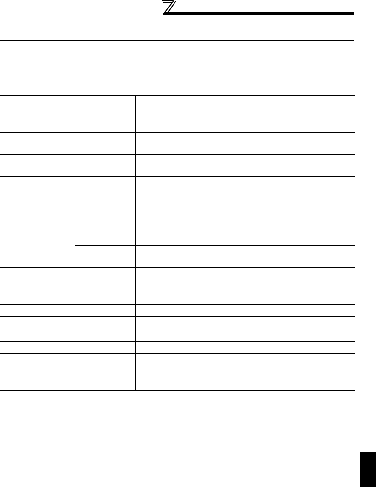
The following table indicates the device names usable with the built-in PLC function
and their ranges of use.
Table 3.3 Device List
Input (X) 64 (X0 to X3F) <12 points installed>
Output (Y) 64 (Y0 to Y3F) <7 points installed>
Internal relay (M) 64 (M0 to M63)
Latch relay (L)
None (Can be set with built-in PLC function parameters
but will not latch)
Step relay (S)
None (Can be set with built-in PLC function parameters
but will operate as M)
Link relay (B) None
Timer (T)
Points 16(T0 to T15)
Specifications
100ms timer: Set time 0.1 to 3276.7s
10ms timer: Set time 0.01 to 327.67s
100ms retentive timer: Set time 0.1 to 3276.7s
Counter (C)
Points 16(C0 to T15)
Specifications
Normal counter: Setting range 1 to 32767
Interrupt program counter: None
Data device (D) 120(D0 to D119)
Link register (W) None
Annunciator (F) None
File register (R) None
Accumulator (A) None
Index register (Z, V) None
Pointer (P) None
Interrupt pointer (I) None
Special relay (M) 256 (M9000 to 9255) with function limit
Special register (D) 256 (D9000 to 9255) with function limit