


9 - 24 9 - 24
MELSEC-Q
9 LOADING AND INSTALLATION
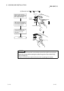
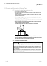
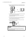
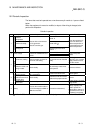
(b) Do not connect the 24VDC outputs of two or more power supply modules in
parallel to supply power to one I/O module. Parallel connection will damage
the power supply modules.
24VDC
24VDC
24VDC
Power supply
module
Power supply
module
I/O module
I/O module
Power supply
module
External power supply
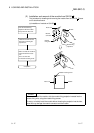
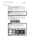
(c) 100VAC, 200VAC and 24VDC wires should be twisted as dense as possible.
Connect the modules with the shortest distance.
Also, to reduce the voltage drop to the minimum, use the thickest wires
possible (maximum 2mm
2
).
(d) Do not bundle the 100VAC and 24VDC wires with, or run them close to, the
main circuit (high voltage, large current) and I/O signal lines. Reserve a
distance of at least 100 mm from adjacent wires.
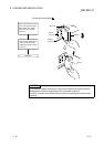
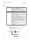
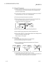
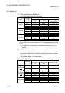
(e) As a countermeasure to power surge due to lightening, connect a surge
absorber for lightening as shown below.
AC
E1
E2
Surge absorber for lightening
PLC
POINT
(1) Separate the ground of the surge absorber for lightening (E1) from that of the
PLC (E2).
(2) Select a surge absorber for lightening whose power supply voltage does no
exceed the maximum allowable circuit voltage even at the time of maximum
power supply voltage elevation.