


11 - 97 11 - 97
MELSEC-Q
11 TROUBLESHOOTING
Special Register List (Continue)
ACPU
Special
Conversion
Special
Register after
Conversion
Special
Register for
Modification
Name Meaning Details
Corresponding
CPU
D9248 SD1248
Stores conditions
for up to numbers 1
to 16
D9249 SD1249
Stores conditions
for up to numbers
17 to 32
D9250 SD1250
Stores conditions
for up to numbers
33 to 48
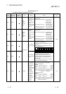
D9251 SD1251
Local station
operation
status
Stores conditions
for up to numbers
49 to 64
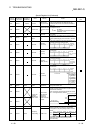
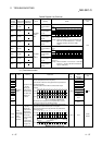
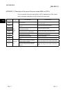
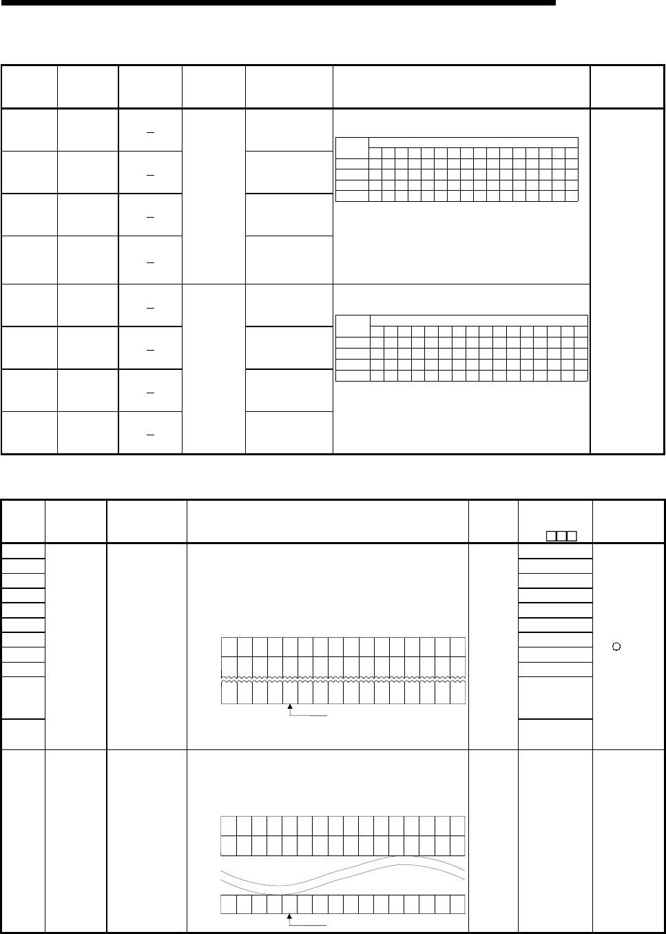
Stores the local station number which is in STOP or PAUSE
mode.
SD1248
SD1249
SD1250
SD1251
b15 b14 b13 b12 b11 b10 b9 b8 b7 b6 b5 b4 b3 b2 b1 b0
L16 L15 L14 L13 L12 L11
L32 L31 L30 L29 L28 L27
L48 L47 L46 L45 L44 L43
L64 L63 L62 L61 L60 L59
L26
L42
L58
L25
L41
L57
L24
L40
L56
L23
L39
L55
L22
L38
L54
L21
L37
L53
L20
L36
L52
L19
L35
L51
L18
L34
L50
L17
L33
L49
L10 L9 L8 L7 L6 L5 L4 L3 L2 L1
Bit
Device
number
The bit corresponding to the station number which is in
STOP or PAUSE mode, becomes "1".
Example: When local stations 7 and 15 are in STOP mode,
bits 6 and 14 of SD1248 become "1", and when
SD1248 is monitored, its value is "16448
(4040
H
)".
D9252 SD1252
Stores conditions
for up to numbers 1
to 16
D9253 SD1253
Stores conditions
for up to numbers
17 to 32
D9254 SD1254
Stores conditions
for up to numbers
33 to 48
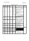
D9255 SD1255
Local station
error
conditions
Stores conditions
for up to numbers
49 to 64
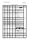
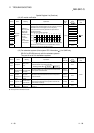
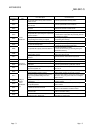
Stores the local station number other than the host, which is
in error.
SD1252
SD1253
SD1254
SD1255
b15 b14 b13 b12 b11 b10 b9 b8 b7 b6 b5 b4 b3 b2 b1 b0
L16 L15 L14 L13 L12 L11
L32 L31 L30 L29 L28 L27
L48 L47 L46 L45 L44 L43
L64 L63 L62 L61 L60 L59
L26
L42
L58
L25
L41
L57
L24
L40
L56
L23
L39
L55
L22
L38
L54
L21
L37
L53
L20
L36
L52
L19
L35
L51
L18
L34
L50
L17
L33
L49
L10 L9 L8 L7 L6 L5 L4 L3 L2 L1
Bit
Device
number
The bit corresponding to the station number which is in error,
becomes "1".
Example: When local station 12 is in error, bit 11 of SD1252
becomes "1", and when SD1252 is monitored, its
value is "2048 (800
H
) ".
QnA
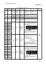
(11) Fuse blown module
Number Name Meaning Explanation
Set by
(When
set)
Corresponding
ACPU
D9
Corresponding
CPU
SD1300 D9100
SD1301 D9101
SD1302 D9102
SD1303 D9103
SD1304 D9104
SD1305 D9105
SD1306 D9106
SD1307 D9107
SD1308 New
SD1309
to
SD1330
New
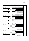
SD1331
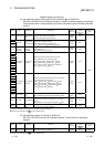
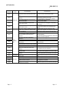
Fuse blown
module
Bit pattern in units
of 16 points,
indicating the
modules whose
fuses have blown
0: No blown fuse
1: Blown fuse
present
• The numbers of output modules whose fuses have blown are
input as a bit pattern (in units of 16 points).
(If the module numbers are set by parameter, the parameter-set
numbers are stored.)
• Also detects blown fuse condition at remote station output
modules
1514131211109876543210
0
0
0
1
(YC0)
000 00000000
1
(Y80)
SD1300
00
1
(Y1F0)
0 0 00000000
1
(Y1A)
SD1301
00
00
1
(Y1F
B0)
00000000
SD1331
000
1
(Y1F
30)
0
Indicates a blown fuse
• Not cleared even if the blown fuse is replaced with a new one.
This flag is cleared by error resetting operation.
S (Error)
New
+Rem
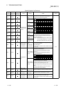
SD1350
to
SD1381
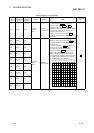
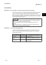
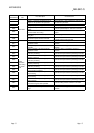
External
power supply
disconnected
module
(For future
expansion)
Bit pattern in units
of 16 points,
indicating the
modules whose
external power
supply has been
disconnected
0: External power
supply
disconnected
1: External power
supply is not
disconnected
The module number (in units of 16 points) whose external power
supply has been disconnected is input as a bit pattern.
(If the module numbers are set by parameter, the parameter-set
numbers are used.)
15 14 13 12 11 10 9 8 7 6 5 4 3 2 1 0
SD1350
SD1351
0001000 000000001
00
1
0 0 00000000
1
00
SD1381 00 1 0 0000 00000010
Indicates a blown fuse
S (Error) New
QCPU
Remote