


5 - 11 5 - 11
MELSEC-Q
5 POWER SUPPLY MODULE
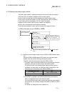
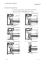
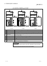
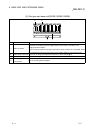
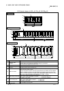
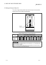
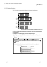
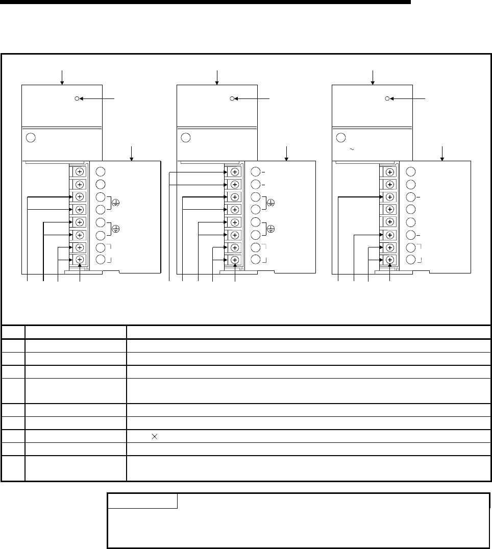
(2) A1S61PN, A1S62PN and A1S63P
MELSECA
1S61PN
POWER
MITSUBISHI
INPUT
100-240VAC
105VA
50 / 60Hz
OUTPUT
5VDC 5A
INPUT
100-240VAC
(FG)
(LG)
A1S61PN
NC
NC
8)
1)
9)
3) 4) 5) 7)
A1S61PN
MELSECA
1S62PN
POWER
MITSUBISHI
INPUT
100-240VAC
105VA
50 / 60Hz
OUTPUT
5VDC 3A
24VDC 0.6A
+24V
24G
INPUT
100-240VAC
(FG)
(LG)
A1S62PN
8)
1)
9)
3) 4) 5) 7)
2)
A1S62PN
MELSECA
1S63P
POWER
MITSUBISHI
INPUT
DC15.6 31.2V
OUTPUT
DC 5V 5A
FG
LG
INPUT
+24V
24G
NC
NC
NC
NC
8)
1)
9)
3) 4) 6) 7)
A1S63P
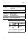
No. Name Application
1) POWER LED 5VDC power indicator LED
2) +24V, 24G terminals Used to supply 24VDC power to inside the output module (using external wiring).
3) FG terminals Ground terminal connected to the shield pattern of the printed circuit board.
4) LG terminals
Grounding for the power supply filter. The potential of A1S61PN or A1S62PN terminal is
1/2 of the input voltage.
5) Power input terminals Used to connect a 100VAC to 200VAC power supply.
6) Power input terminals Used to connect a 24 VDC power supply.
7) Terminal screw M3.5 7 screw
8) Terminal cover Protective cover of the terminal block
9) Module fixing screw
Used to fix the module to the base unit.
(M4 screw, tightening torque : 66 to 89N•cm)
POINTS
(1) Do not wire to those terminals for which NC is stamped on the terminal block.
(2) Ensure that the earth terminals LG and FG are grounded.