


8 - 6 8 - 6
MELSEC-Q
8 EMC AND LOW VOLTAGE DIRECTIVE
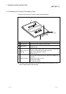
(b) Positioning modules
Precautions to be followed when the machinery conforming to the EMC
Directive is configured using the A1SD75P1-S3/A1SD75P2-S3/A1SD75P3-
S3 (hereafter referred to as the A1SD75) are described below.
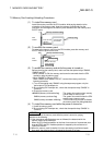
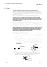
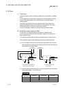
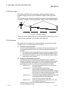
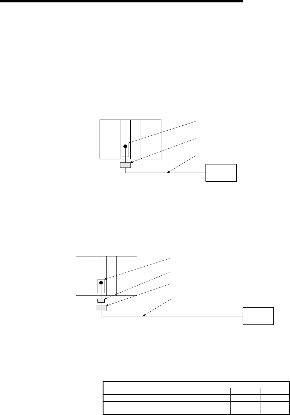
1) When wiring with a 2 m (6.56 ft.) or less cable
• Ground the shield section of the external wiring cable with the cable
clamp. (Ground the shield at the closest location to the A1SD75
external wiring connector.)
• Wire the external wiring cable to the drive unit and external device with
the shortest practicable length of cable.
• Install the drive unit in the same panel.
Power supply
module
A1SD75
module
Drive unit
External wiring connector
Cable clamp
External wiring cable (within 2 m (6.56 ft.))
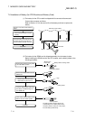
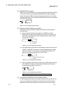
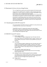
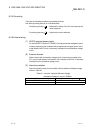
2) When wiring with cable that exceeds 2 m (6.56 ft.), but is 10 m (32.79 ft.)
or less
• Ground the shield section of the external wiring cable with the cable
clamp. (Ground the shield at the closest location to the A1SD75
external wiring connector.)
• Install a ferrite core.
• Wire the external wiring cable to the drive unit and external device with
the shortest practicable length of cable.
External wiring connector
Ferrite core
External wiring cable (2 m to 10 m (6.56 ft. to 32.79 ft.))
Cable clamp
Power supply
module
A1SD75
module
Drive unit
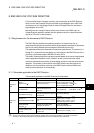
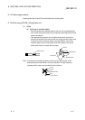
3) Ferrite core and cable clamp types and required quantities
• Cable clamp
Type : AD75CK (Mitsubishi Electric)
• Ferrite core
Type : ZCAT3035-1330 (TDK ferrite core)
• Required quantity
Required Qty
Cable length Prepared part
1 axis 2 axes 3 axes
Within 2 m (6.56 ft.) AD75CK 1 1 1
AD75CK 1 1 1 2 m (6.56 ft.) to 10m
(32.79ft.)
ZCAT3035-1330 1 2 3