


11 - 92 11 - 92
MELSEC-Q
11 TROUBLESHOOTING
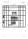
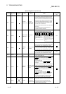
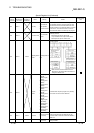
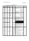
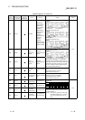
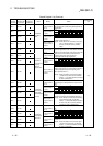
Special Register List (Continued)
ACPU
Special
Conversion
Special
Register after
Conversion
Special
Register for
Modification
Name Meaning Details
Corresponding
CPU
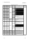
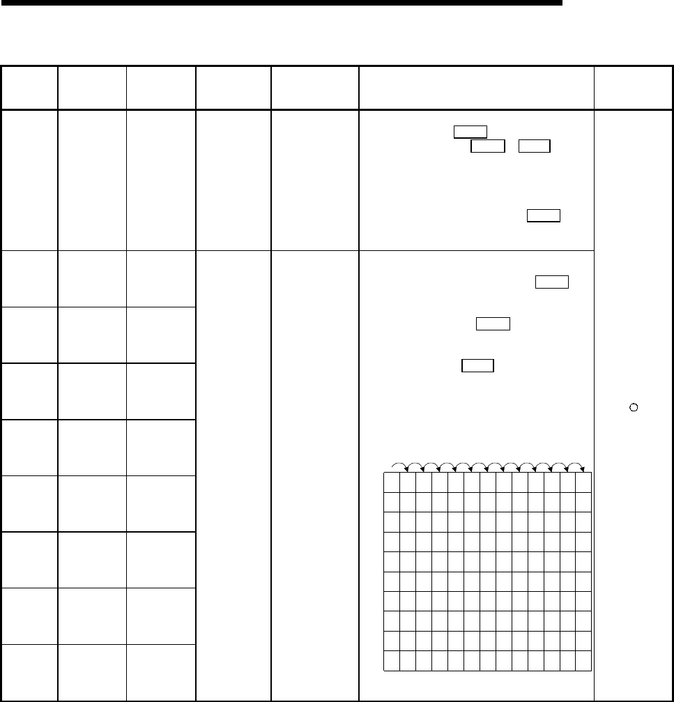
D9124 SD1124 SD63
Annunciator
detection
quantity
Annunciator
detection quantity
• When one of F0 to 2047 (F0 to 2047 for AuA and
AnU) is turned on by SET F 1 is added to the
contents of SD63. When RST F or LEDR
instruction is executed, 1 is subtracted from the
contents of SD63. (If the INDICATOR RESET switch
is provided to the CPU, pressing the switch can
execute the same processing.)
• Quantity, which has been turned on by SET F is
stored into SD63 in BIN code. The value of SD63 is
maximum 8.
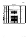
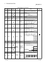
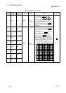
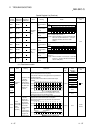
D9125 SD1125 SD64
D9126 SD1126 SD65
D9127 SD1127 SD66
D9128 SD1128 SD67
D9129 SD1129 SD68
D9130 SD1130 SD69
D9131 SD1131 SD70
D9132 SD1132 SD71
Annunciator
detection
number
Annunciator
detection number
• When any of F0 to 2047 is turned ON by SET F , F
numbers turned ON sequentially are registered into
D9125 - D9132.
F numbers turned OFF by RST F are deleted from
D9125 - D9132, and move to data registers
subsequent to the ones that stored deleted F
numbers. Execution of LEDR instruction shifts up
SD64 - SD71 contents one place. (When CPU has
INDICATOR RESET switch, pressing that switch
performs the same processing.) When there are eight
annunciator numbers detected, the ninth number is
not stored into SD64 - SD71 if detected.
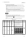
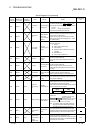
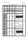
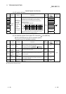
0 505050505050505050505099
0
0 5050505050505050505099
0 2525999999999999999915
123234567888
50
0
0 99 1515151515151570
00 0
0 70707070707065
00 000
0 65656565653800 0000
0 38383838
110
00 0000
0
0 110 110 110
151
00 0000
0
0 151151 210
00 0000
0
0
00
S
D62
S
D63
S
D64
S
D65
S
D66
S
D67
S
D68
S
D69
S
D70
S
D71
SET
F50
SET
F25
SET
F99
RST
F25
SET
F15
SET
F70
SET
F65
SET
F38
SET
F110
SET
F151
SET
F210 LEDR