


9 - 14 9 - 14
MELSEC-Q
9 LOADING AND INSTALLATION
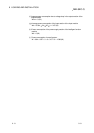
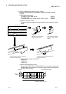
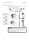
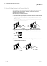
(2) Module mounting orientation
(a) Since the PLC generates heat, it should be mounted on a well ventilated
location in the orientation shown below.
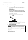
(b) Do not mount it in either of the orientations shown below.
Vertical Flat
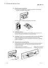
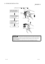
(3) Installation surface
Mount the base unit on a flat surface. If the mounting surface is not even, this
may strain the printed circuit boards and cause malfunctions.
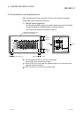
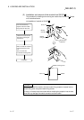
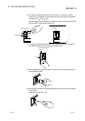
(4) Installation of unit in an area where the other devices are installed
Avoid mounting base unit in proximity to vibration sources such as large
magnetic contractors and no-fuse circuit breakers; mount these on a separate
panel or at a distance.
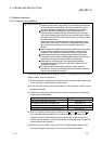
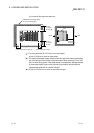
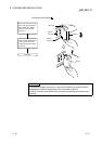
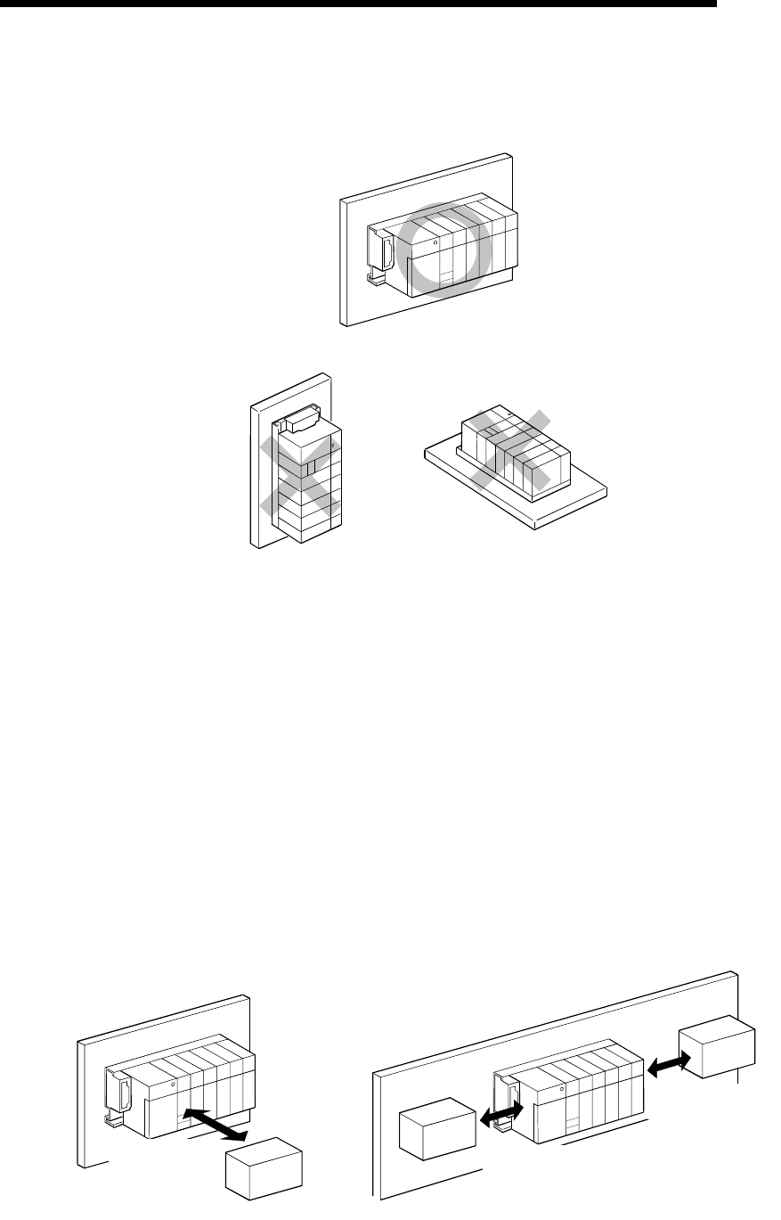
(5) Distances from the other devices
In order to avoid the effects of radiated noise and heat, provide the clearances
indicated below between the PLC and devices that generate noise or heat
(contactors and relays).
• Required clearance in front of PLC : at least 100 mm (3.94 inch)
• Required clearance on the right and left of PLC : at least 50 mm (1.97 inch)
Contactor, relay, etc.
At least 100mm
(3.94 inch)
At least 50mm
(1.97 inch)
At least 50mm
(1.97 inch)