


11 - 35 11 - 35
MELSEC-Q
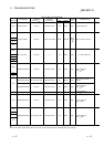
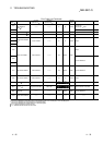
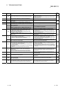
11 TROUBLESHOOTING
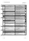
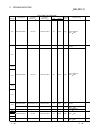
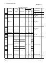
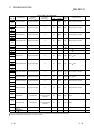
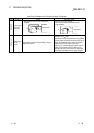
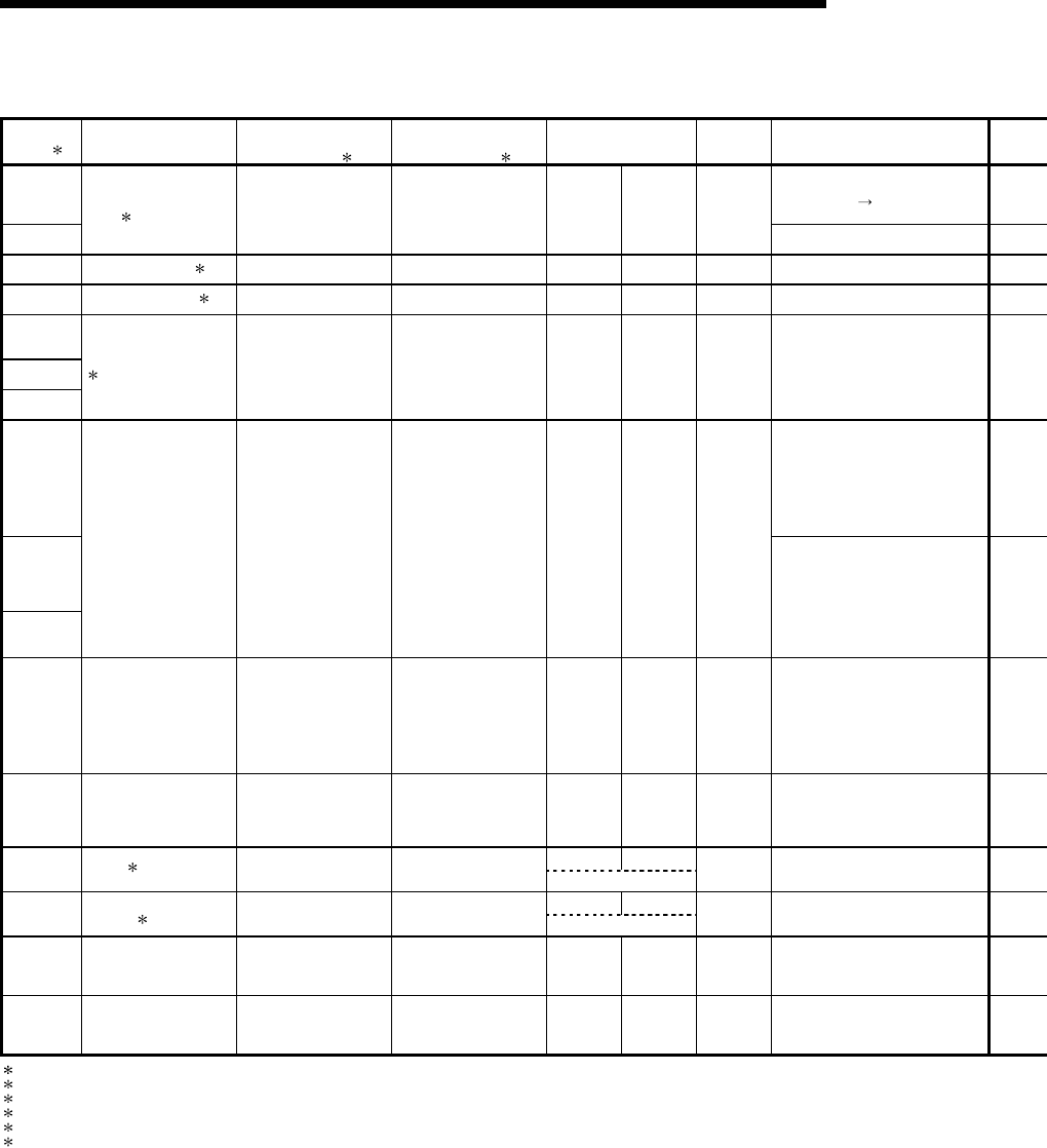
Error Code List (Continued)
Error Code
(SD0)
1
Error Messages
Common
Information
(SD5 to 15)
1
Individual
Information
(SD16 to 26) 1
LED Status
Operating
Statuses of
CPU
Diagnostic Timing
6100
At power on/
Reset/STOP
RUN
6101
TRK. MEMORY
ERR.
3
——— ——— on on Continue
When END instruction executed
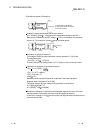
6200 CONTROL EXE.
4
Cause of switch ——— on off Continue Always
6210 CONTROL WAIT. 5 Cause of switch ——— on off Continue Always
6220
6221
6222
CAN'T EXE CHANGE
4
Cause of switch ——— on on Continue Always
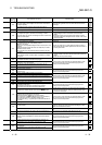
7000 Always
7002
At power ON/Reset
7003
MULT CPU DOWN Unit/module No. ——— Off Flicker Stop
7010 MULTI EXE. ERROR Unit/module No. ——— Off Flicker Stop At power ON/Reset
7020 MULTI CPU ERROR Unit/module No. ——— On On Continue Always
On Off
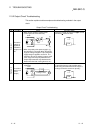
9000 F
∗∗∗∗
6 Program error location Annunciator number
USER LED On
Continue When instruction is executed
On Off
9010
<CHK> ERR
∗∗∗
-
∗∗∗
7
Program error location Failure No.
USER LED On
Continue When instruction is executed
9020 BOOT OK ——— ——— Off Flicker Stop At power ON/Reset
10000 CONT. UNIT ERROR ——— ——— ——— ——— ——— ———
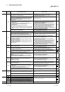
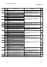
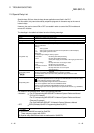
1 Characters in parentheses ( ) indicate the special register numbers where individual information is being stored.
3 Can only be detected in a redundant system. Can be detected either in the control system or the standby system.
4 Can only be detected in the control system of a redundant system.
5 Can only be detected in the standby system of a redundant system.
6
∗∗∗∗
indicates detected annunciator number.
7
∗∗∗
indicates detected contact and coil number.