


6 - 7 6 - 7
MELSEC-Q
6 BASE UNIT AND EXTENSION CABLE
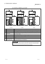
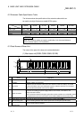
6.5 I/O Number Allocation
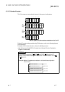
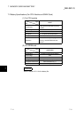
The I/O numbers are automatically allocated in the system loading status.
O
U
T
X/Y
0
X/Y
20
X/Y
40
X/Y
60
X/Y
80
X/Y
C0
X/Y
E0
X/Y
100
X/Y
120
X/Y
140
X/Y
160
X/Y
180
01234
6 7 8 9 10 11 125
X/Y
A0
X/Y
1C0
X/Y
1E0
X/Y
200
X/Y
220
X/Y
240
X/Y
260
X/Y
280
14 15 16 17 18 19 2013
X/Y
1A0
X/Y
2C0
X/Y
2E0
X/Y
300
X/Y
320
22 23 24 2521
X/Y
2A0
1st
extension
stage
I
N
O
U
T
Power supply
module
CPU
module
Power supply
module
Power supply
module
Power supply
module
I
N
O
U
T
I
N
O
U
T
2nd
extension
stage
3rd
extension
stage
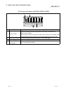
In this system, 32-point modules are loaded on slots 0 to 25.
For the I/O number setting method using GX Developer, refer to the Operating Manual
of GX Developer.
For details of I/O number allocation, refer to the following manual.
• High Performance Model QCPU (Q mode) User's Manual (Function Explanation,
Program Fundamentals)
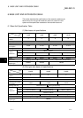
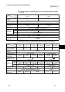
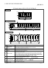
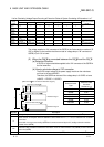
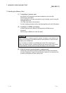
POINT
For the extension using the Q5 B, Q6B B and QA1S6 B, allocate the I/O
numbers on the modules starting from the Q series module installed on the Q5
B,
Q6
B base unit.
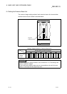
<Example> Where 32 modules are installed in all slots with the configuration
shown below.
Q38B main base unit
Q68B extension base unit
QA1S68B extension base unit
QA1S68B extension base unit
00 to FF
100 to 1FF
200 to 2FF
300 to 3FF