


9 - 25 9 - 25
MELSEC-Q
9 LOADING AND INSTALLATION
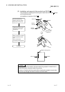
(2) Wiring of I/O equipment
(a) Insulation-sleeved crimping terminals cannot be used with the terminal block.
It is recommended to cover the wire connections of the crimping terminals
with mark or insulation tubes.
(b) The wires used for connection to the terminal block should be 0.3 to 0.75mm
2
in core and 2.8mm (0.11 inch) max. in outside diameter.
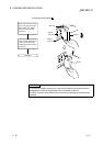
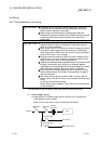
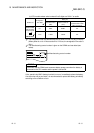
(c) Run the input and output lines away from each other.
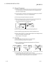
(d) When the wiring cannot be run away from the main circuit and power lines,
use a batch-shielded cable and ground it on the PLC side.
In some cases, ground it in the opposite side.
Input
Output
PLC
Shielded cable
Shield
DC
RA
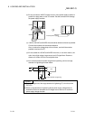
(e) Where wiring runs through piping, ground the piping without fail.
(f) Run the 24VDC input line away from the 100VAC and 200VAC lines.
(g) Wiring of 200m (686.67 ft.) or longer distance will give rise to leakage currents
due to the line capacity, resulting in a fault.
Refer to Section 11.5 for details.
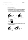
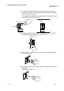
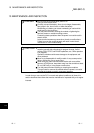
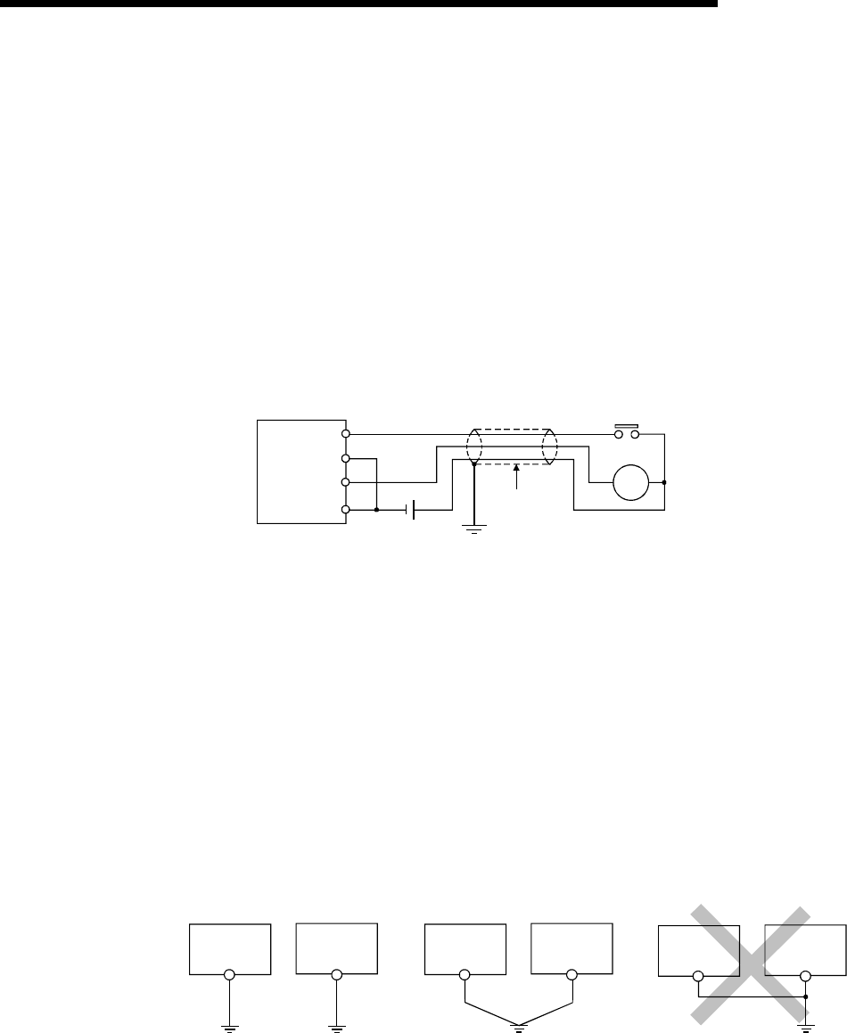
(3) Grounding
To ground the cable, follow the steps (a) to (c) shown below.
(a) Use the dedicated grounding as far as possible.
(b) When a dedicated grounding cannot be performed, use (2) Common
Grounding shown below.
PLC
Another
equipment
grounding
(1) Independent grounding.....Best (2) Common grounding.....Good (3) Joint grounding.....Not allowe
d
PLC
Another
equipment
PLC
Another
equipment
grounding
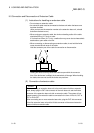
(c) For grounding a cable, use the cable of 2 mm
2
or more.
Position the ground-contact point as closely to the sequencer as possible, and
reduce the length of the grounding cable as much as possible.