


11 - 21 11 - 21
MELSEC-Q
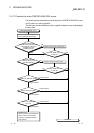
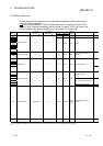
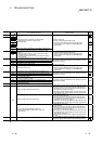
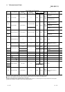
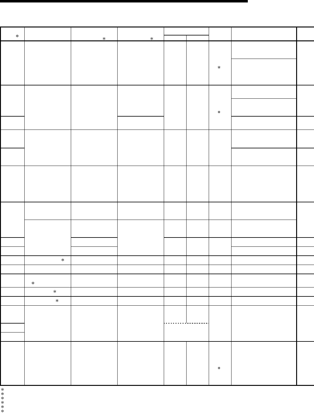
11 TROUBLESHOOTING
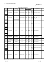
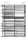
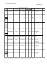
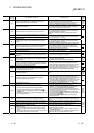
Error Code List (Continued)
LED Status
Error Code
(SD0)
1
Error Messages
Common
Information
(SD5 to 15)
1
Individual
Information
(SD16 to 26) 1
RUN ERROR
Operating
Statuses of
CPU
Diagnostic Timing
At power ON/At reset/
When intelligent function module
is accessed.
1401 SP. UNIT DOWN Unit/module No. ——— Off/On Flicker/On
Stop/
Continue
3
At power ON/At reset
When an intelligent function
module access instruction is
executed.
1402 Program error location
During execution of FROM/TO
instruction set.
1403
SP. UNIT DOWN Unit/module No.
———
Off/On Flicker/On
Stop/
Continue
6
When an END instruction is
executed.
1411 At power ON/At reset
1412
CONTROL-BUS ERR. Unit/module No. Program error location Off Flicker Stop
During execution of FROM/TO
instruction set.
1413 CONTROL-BUS. ERR. ——— ——— off Flicker Stop Always
CONTROL-BUS. ERR. Unit/module No. ——— Off Flicker Stop
When an END instruction is
executed.
1414
——— off Flicker Stop
When an END instruction is
executed
1415 Base No.
When an END instruction is
executed
1416
CONTROL-BUS. ERR.
Unit/module No.
———
Off Flicker Stop
At power ON/At reset
1421 SYS. UNIT DOWN 3 ——— ——— off Flicker Stop Always
1500 AC DOWN ——— ——— On Off Continue Always
1510
DUAL DC DOWN
5V 4
——— ——— on on Continue Always
1520 DC DOWN 5V 5 ——— ——— off Flicker Stop Always
1530 DC DOWN 24V 3 ——— ——— on on Continue Always
1600 ON On
1601
1602
BATTERY ERROR Drive Name ———
BAT.ALM LED On
Continue Always
2000 UNIT VERIFY ERR. Unit/module No. ——— Off/On Flicker/On
Stop/
Continue
2
When an END instruction is
executed.
1 Characters in parentheses ( ) indicate the special register numbers where individual information is being stored.
2 The CPU module operation status when an error occurs can be set at the parameters. (LED display will change accordingly.)
3 This can only be detected in redundant systems. Detection is possible in either the control system or the standby system.
4 This can only be detected in the redundant system control system.
5 This can be detected in either a standalone system or a redundant system. However, in a redundant system it can only be detected in the control system.
6 Stop/continue operation is selectable for each module by setting parameters.