


6 - 4 6 - 4
MELSEC-Q
6 BASE UNIT AND EXTENSION CABLE
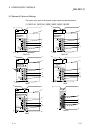
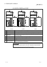
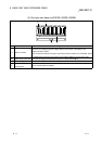
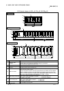
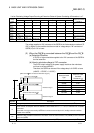
(2) Slim type main base unit(Q32SB, Q33SB, Q35SB)
SG
5V
I/O3I/O2 I/O4I/O0
I/O1
CPU
POWER
5V
56
1)
2)
3)
4)
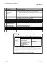
No. Name Application
1) Module connector
Connector for installing the power supply module, CPU module, I/O modules, and
intelligent function module.
To the connectors located in the spare space where these modules are not installed, attach
the supplied connector cover or the blank cover module (QG60) to prevent entry of dirt.
2) Module fixing screw hole Screw hole for fixing the module to the base unit. Screw size:M3 12
3) Base mounting hole Hole for mounting this base unit onto the panel of the control panel (for M4 screw)
4)
DIN rail adapter
mounting hole
Hole for mounting DIN rail adapter