


7 - 6 7 - 6
MELSEC-Q
7 MEMORY CARD AND BATTERY
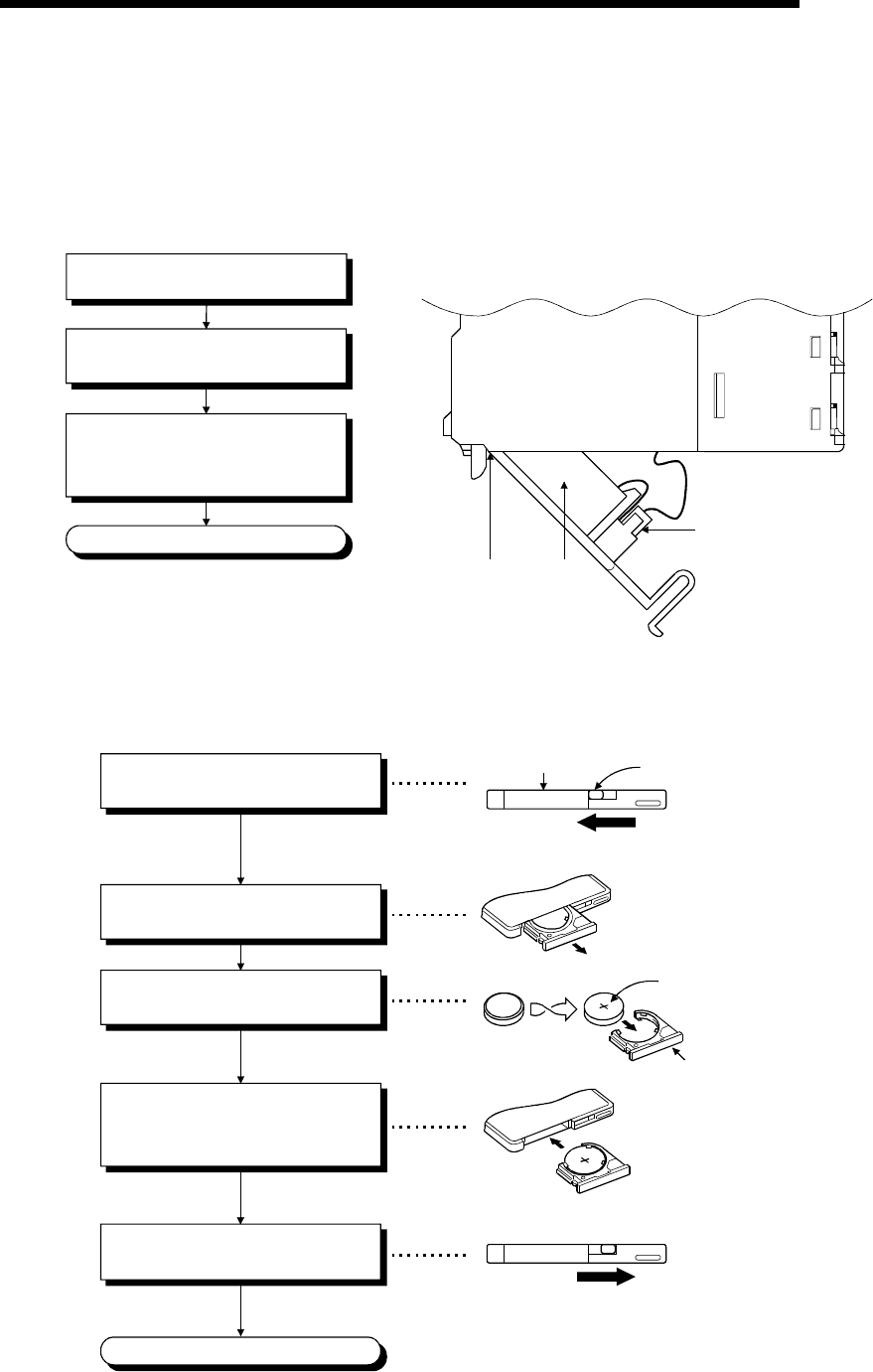
7.6 Installation of Battery (for CPU Module and Memory Card)
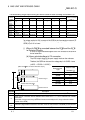
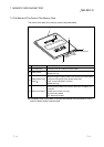
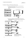
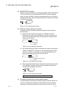
(1) The battery for the CPU module is shipped with its connector disconnected.
Connect the connector as follows.
Refer to Section 10.3 for the service life of the battery and how to replace the
battery.
Side of the CPU module
Open the cover at the CPU module's
bottom.
Confirm that the battery is loaded
correctly.
Insert the battery connector into the
connector pin on the case. Be sure
that the insertion direction is correct.
Completion
Connector
Bottom
Battery
Front
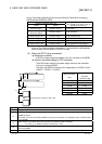
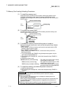
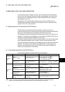
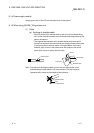
(2) The battery for the SRAM card is shipped separately from the battery holder.
Before installing the SRAM card into the CPU module, set the battery holder in the
following procedure.
'+' sign
"LOCK" position
The battery holder's locking switch is set
automatically to the "LOCK" position when
the battery holder is removed. In its position,
insert the battery holder firmly.
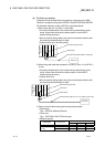
Remove the battery holder from the
SRAM card.
Set the battery onto the battery
holder with the "plus" face up.
Insert the battery holder with which
the battery is installed firmly, into
the SRAM card.
Completion
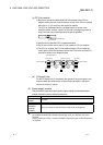
Confirm that the battery holder's locking
switch is set to the "LOCK" position.
Set the battery holder's locking switch
to the "RELEASE" position.
"RELEASE" position
Battery holder's locking switch
"Model name"
on this side
Battery holder