


4 - 6 4 - 6
MELSEC-Q
4 HARDWARE SPECIFICATION OF THE CPU MODULE
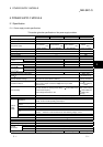
No. Name Application
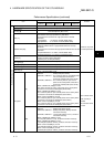
9) Memory card EJECT button Used to eject the memory card from the CPU module.
10)
Memory card loading
connector
Connector used to load the memory card to the CPU module.
11) USB connector 1
Connector for connection with USB-compatible peripheral device. (Connector type B)
Can be connected by USB-dedicated cable.
Not available for Q02CPU.
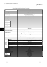
12) RS-232 connector 1
Connector for RS-232 connection
Can be connected by RS-232 connection cable (QC30R2).
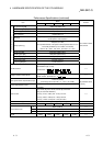
Used to set the items for operation of the CPU module.
For system protection and parameter-valid drive functions, refer to the High
Performance model QCPU (Q mode) User's Manual (Function Explanation, Program
Fundamentals).
SW1 : Used to set system protection. Batch-inhibits write and control directives to the
CPU module. (Shipped in OFF position)
OFF : No protection
ON : Protection
SW2, SW3: Used to specify parameter-valid drive.
(Both SW2 and SW3 are shipped in OFF position)
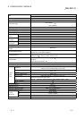
SW2 SW3 Parameter Drive
OFF OFF Program memory (Drive 0)
ON OFF SRAM card (Drive 1)
OFF ON Flash card/ATA card (Drive 2)
ON ON Standard ROM (Drive 4)
Note: Parameters cannot be stored in standard RAM (Drive 3).
SW4 : Must not be used. Normally OFF. (Shipped in OFF position)
13)
DIP switches
1
2
3
4
5
ON SW
SW5 : Must not be used. Normally OFF. (Shipped in OFF position)
14) RUN/STOP switch
RUN : Executes sequence program operation.
STOP : Stops sequence program operation.
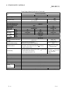
15) RESET/L.CLR switch
RESET : Used to perform hardware reset, operation fault rest, operation initialization,
etc.
If this switch is left in the RESET position, the whole system will be reset and
the system will not operate properly.
After performing reset, always return this switch to the neutral position.
L.CLR : Used to turn "OFF" or "zero" all data in the parameter-set latch area.
Used to clear the sampling trace and status latch registration.
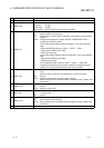
16) Module fixing screw hole Hole for the screw used to fix to the base unit. (M3 12 screw)
17) Module fixing latch Hook used to fix to the base unit.
18) Battery connector pin
For connection of battery lead wires.
(When shipped from the factory, the lead wires are disconnected from the connector to
prevent the battery from consuming.)
19) Battery
Backup battery for use of program memory, standard RAM and power failure
compensation function.
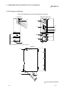
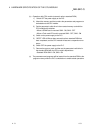
1 : When normally connecting a cable to the USB connector or RS-232 connector, clamp the cable to prevent it from
coming off due to the dangling, moving or carelessly pulling of the cable.
Q6HLD-R2 type RS-232 Connector Disconnection Prevention Holder is available as a clamp for RS-232 connector.
Q6HLD-R2
CPU module
RS-232 cable