


11 - 17 11 - 17
MELSEC-Q
11 TROUBLESHOOTING
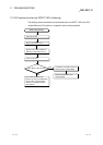
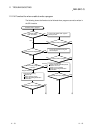
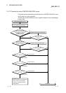
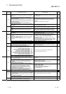
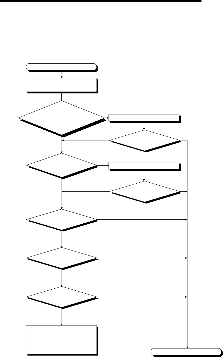
11.2.17 Flowchart for when CONTROL BUS ERR. occurs
The following shows the flowchart to be followed when CONTROL BUS ERR. occurs
at PLC power-on or during operation.
This flow chart can be confirmed only when a specific slot/base unit can be detected by
the error code.
Is the module of the
applicable slot installed properly?
Is the extension cable of the
applicable base unit
installed properly?
Install the module and cable properly.
Is the "ERR." LED
turned off?
CONTROL BUS ERR. occurs.
NO
YES
NO YES
YES
NO YES
NO
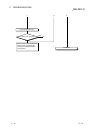
Replace the applicable module.
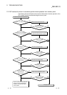
Are all the extension
cables of the base unit
connected properly?
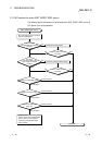
Check the slot base unit where error
occurred with the GX Developer.
Replace the CPU module.
Error detection
Replace the applicable
base unit.
Proper operation
Completion
Hardware fault
Please consult your local Mitsubishi
service center or representative,
explaining a detailed description
of the problem.
Error detection
Error detection
Proper operation
Proper operation
Install the extension cable properly.
Is the "ERR." LED
turned off?