


5 - 4 5 - 4
MELSEC-Q
5 POWER SUPPLY MODULE
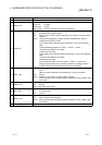
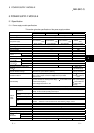
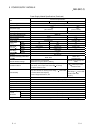
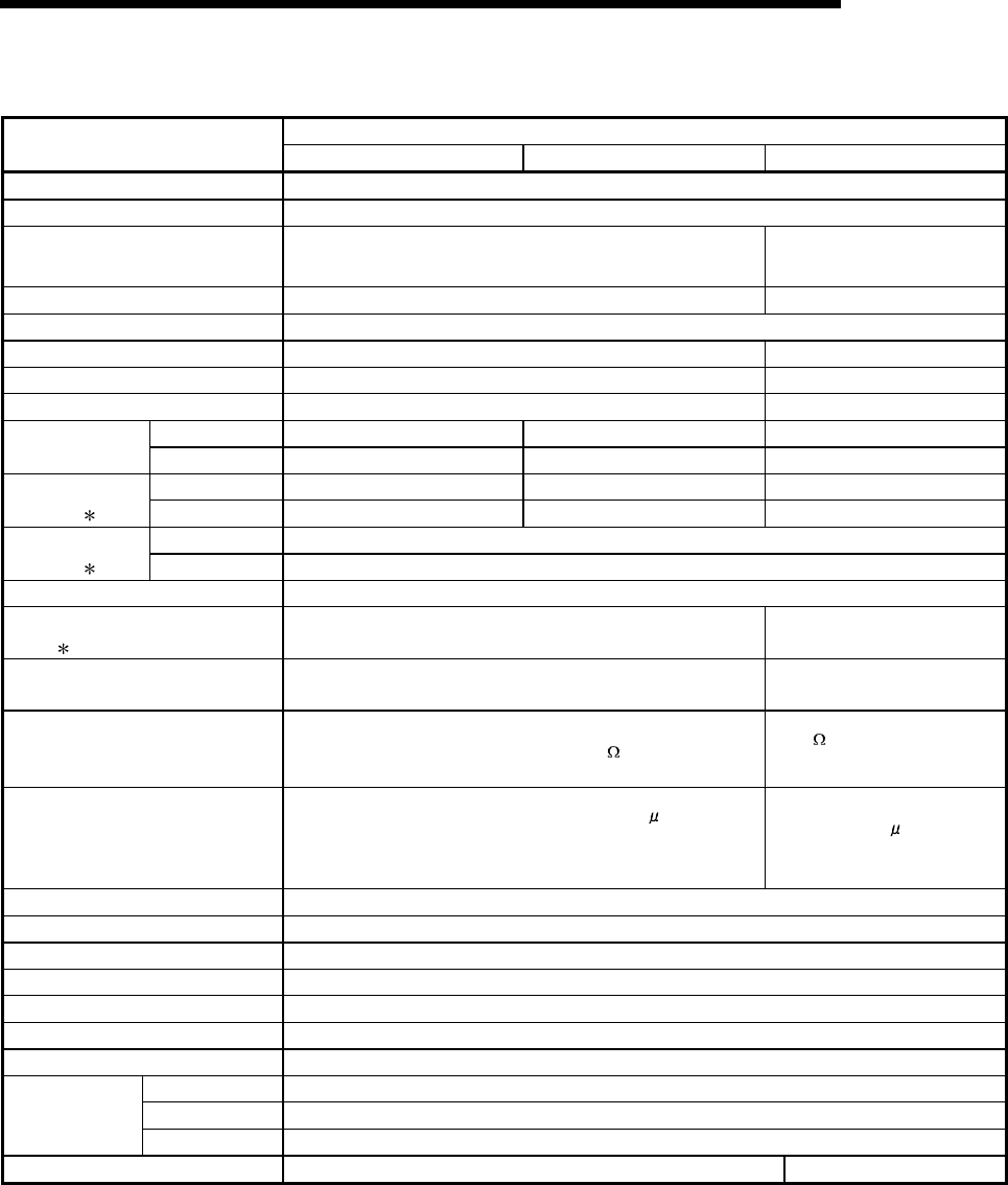
Power Supply Module Specifications (Continued)
Performance Specifications
Item
A1S61PN A1S62PN A1S63P
Base loading position Power supply module loading slot
Applicable base unit QA1S65B, QA1S68B
100 to 240VAC
+10%
-15%
24VDC
+30%
-35%
Input power supply
(85 to 264VAC) (15.6 to 31.2VDC)
Input frequency 50/60Hz ±5% ——
Input voltage distortion factor Within 5%
Max. input apparent power 105VA ——
Max. input power —— 41W
Inrush current 20A within 8ms 81A within 1ms
5VDC 5A 3A 5A Rated output
current
24VDC —— 0.6A ——
5VDC 5.5A or more 3.3A or more 5.5A or more Overcurrent
protection
1
24VDC —— 0.66A or more ——
5VDC 5.5 to 6.5V Overvoltage
protection
2
24VDC ——
Efficiency 65% or more
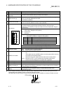
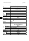
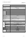
Allowable momentary power failure
period
3
Within 20ms
Within 10ms
(at 24VDC input)
Dielectric withstand voltage
Across inputs/LG and outputs/FG
2830VAC rms/3 cycles (2000 m (6562 ft.))
500VAC across primary and
5VDC
Insulation resistance
Across inputs and outputs (LG and FG separated), across inputs
and LG/FG, across outputs and FG/LG 10M or more by
insulation resistance tester
5M
or more by insulation
resistance tester
Noise durability
• By noise simulator of 1500Vp-p noise voltage, 1
s noise width
and 25 to 60Hz noise frequency
• Noise voltage IEC61000-4-4, 2kV
By noise simulator of 500Vp-p
noise voltage, 1
s noise width
and 25 to 60Hz noise
frequency
Operation indication LED indication (lit at 5VDC output)
Fuse Built-in (Unchangeable by user)
Contact output section No
Terminal screw size M3.5 × 7
Applicable wire size 0.75 to 2mm
2
Applicable solderless terminal RAV1.25 to 3.5, RAV2 to 3.5
Applicable tightening torque 66 to 89N•cm
H 130mm (5.12inch)
W 55mm (2.17inch)
External
dimensions
D 93.6mm (3.69inch)
Weight 0.60kg 0.50kg