


6 - 5 6 - 5
MELSEC-Q
6 BASE UNIT AND EXTENSION CABLE
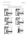
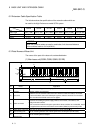
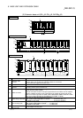
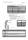
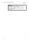
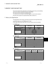
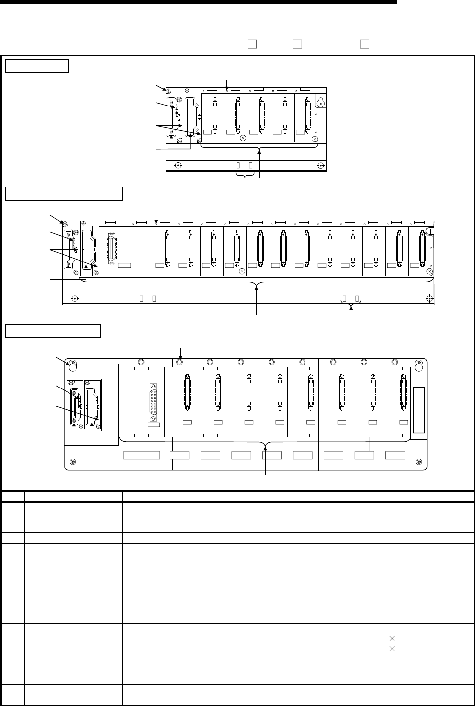
(3) Extension base unit (Q5 B, Q6 B, QA1S6 B)
Q52B, Q55B
I/O2I/O1I/O0 I/O3 I/O4
OUTIN
6)
3)
2)
1)
7) 4)
5)
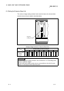
Q63B,Q65B, Q68B, Q612B
6)
3)
5)
2)
4) 7)
I/11I/10I/09I/08I/07I/06I/05I/04I/03I/02I/01I/00
POWER
5V
56
1)
OUTIN
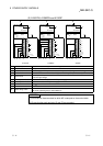
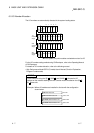
QA1S65B, QA1S68B
I/O0 I/O7I/O6I/O5I/O4I/O3I/O2I/O1
QA1S68B
6)
3)
2)
1)
5)
4)
POWER
5V
SG
FG
IN OUT
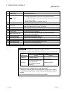
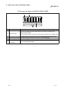
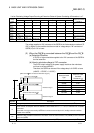
No. Name Application
1)
Extension cable
connector
Connectors for sending and receiving signals from the main base unit or the other
extension base units, to which the extension cables are connected.
Do not remove the supplied connector cover.
2) Base cover Protective cover of extension cable connector.
3)
Stage No. setting
connector
Connector for setting the number of stages of the extension base unit.
For setting method, refer to Section 6.4.
4) Module connector
Connectors for installing the power supply module, I/O modules, and intelligent function
module/ special function module.
To those connectors located in the spare space where these modules are not installed,
apply the supplied connector cover or the blank cover module to prevent entry of dirt.
Blank cover module applicable to Q52B, Q55B, Q63B,Q65B, Q68B and Q612B :QG60
Blank cover module applicable to QA1S65B and QA1S68B :A1SG60
5) Module fixing screw hole
Screw hole for fixing the module to the base unit.
Q52B, Q55B, Q63B,Q65B,Q68B and Q612B.............Screw size: M3 12
QA1S65B and QA1S68B.............................................Screw size: M4 12
6) Base mounting hole
Hole for mounting this base unit on the panel of the control panel.
Q52B, Q55B, Q65B,Q68B and Q612B ..........For M4 screw
QA1S65B and QA1S68B................................For M5 screw
7)
DIN rail adapter
mounting hole
DIN rail adapter mounting hole.