


USER’S GUIDE
050396 99/173
100
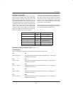
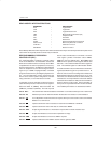
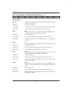
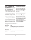
READ–MODIFY–WRITE INSTRUCTIONS
MNEMONIC DESCRIPTION
ANL – Logical AND
ORL – Logical OR
XRL – Logical Exclusive OR
JBC – Branch if Bit Set and Clear (bit)
CPL – Complement Bit
INC – Increment
DEC – Decrement
DJNZ – Decrement and Branch if not Zero
MOV PX.n,C – Move Carry Bit to bit n of Port X
CLR PX.n – Clear bit n in Port X
SETB PX.n – Set bit n in Port X
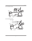
Read–Modify–Write instructions input the state of the latch rather than the pin so that the operation takes place on the
value which was originally written to the latch by the software.
REPROGRAMMABLE PERIPHERAL
CONTROLLER (RPC)
The Reprogrammable Peripheral Controller (RPC)
mode of the DS5001FP and DS5002FP emulate the
8042 slave hardware interface commonly used in IBM–
compatible PCs for control of peripherals such as a key-
board or a mouse device. In addition to a direct interface
to the PC backplane bus, the device brings the advan-
tages of up to 128KB of reprogrammable, nonvolatile
program and data memory to intelligent peripheral con-
trol. The nonvolatile data memory accessed by the
device can be used for system configuration, hard disk
setup parameters, or even maintenance records.
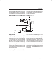
In operating as a slave controller, the device communi-
cates with a host processor via three resource registers:
Data Bus Buffer In (DBBIN), Data Bus Buffer Out
(DBBOUT), and Status (STATUS). The host may read
data or status and write data or commands. The STA-
TUS register provides information about DBBIN,
DBBOUT, and user–defined flags. Both DBBIN and
DBBOUT share special function register address 80H
with Port 0. The context will determine which register is
used. The STATUS register is at SFR location 0DAH.
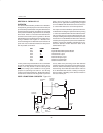
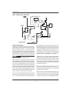
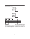
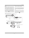
To enable the RPC mode, the RPCON bit in the RPCTL
register (described in Figure 12–6) must be set to a 1. At
this time, Ports 0 and 2 are reconfigured to emulate the
8042 hardware interface as shown in Figure 12–3. Port
0 becomes an 8–bit data bus that can connect directly to
a PC data bus. Port 2 provides the control and address
information for the data bus. Both ports are true bidirec-
tional I/O devices in this mode. Normal operation of
these ports is suspended when RPC mode is enabled.
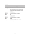
The modified port functions are described as follows:
Port 0: D0–7 This is the 8–bit bi–directional data bus of the RPC. It can interface directly to a PC or other host.
Port 2.0: A0 Address input used to determine whether the data bus word is data or command/status.
Port 2.1: CE
If a multiple RPC mode environment is required, this input can be used to select an individual
DS5001 on a common bus.
Port 2.2: RD Input that allows the host to read data or status from the DBBOUT or STATUS.
Port 2.3: WR Input that allows the host to write data or commands to DBBIN.
Port 2.4: OBF Output flag that indicates to a host that the output buffer is full and should be read.
Port 2.5: IBF Output that indicates to a host that the input buffer is empty.
Port 2.6: DRQ Output that indicates to a host that a DMA is required.
Port 2.7: DACK
Input that indicates to the DS5001 that the host has granted a DMA.