


USER’S GUIDE
050396 152/173
153
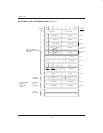
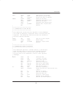
The time, calendar, and alarms are controlled by the
information in these 14 registers. In particular, the Com-
mand register controls most functions. This is described
in Figure 17–8. There are two additional bits that
deserve mention. These reside in the register at
address 09h. Bit 7 is EOSC
, which enables the Time-
keeping oscillator if set to a 0. Battery lifetime can be
preserved by disabling the oscillator when it is not
needed and power is not present. Note the user’s soft-
ware should enable the oscillator, as it should be off for
shipping. If the oscillator is off, a user can read or write
to the Timekeeping register, but the time value will not
change. Bit 6 of the same register is the ESQW
bit. This
controls the timekeeper 1024 Hz SQW output. The
SQW signal is available on the DS2251T. When it is
enabled, it drives a square wave of 1024 Hz. When dis-
abled, it is tri–state so it will not interfere with other uses
of a port pin.
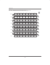
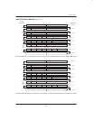
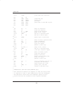
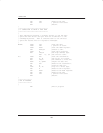
DS1283 REAL–TIME CLOCK COMMAND REGISTER Figure 17–8
RTC COMMAND Register Address 0BH
TE IPSW IBH/L0 PU/LVL WAM TDM WAF TDF
CMD.7: TE
Transfer Enable To avoid updating of time registers while a read is taking place, the update
may be frozen. Setting the TE bit to a logic 0 will prevent an update of the
user–readable registers from the actual time of day. Setting TE to a logic 1
will enable updates every 0.01 seconds.
CMD.6: IPSW
Interrupt Switch When set to a logic 1, INTP
will be assigned to time of day alarm and INTB
will be assigned to the periodic time–out. When set to a logic 0, the functions
are reversed.
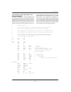
CMD.5: IBHL
INTB H/L When set to logic 1, the INTB
will source current (active high). When set to a
logic 0, INTB will sink current (active low).
CMD.4: PU/LVL
Pulse/Level When set to a logic 1, INTP
will sink current for approximately 3 ms when it is
activated. INTB will sink or source (as set by IBLH) for 3 ms. When set to a
logic 0, the interrupt pins will signal with a continuous level.
CMD.3: WAM
Watchdog Alarm When set to a logic 1, the watchdog countdown timer interrupt will be
Mask disabled. When set to a logic 0, the countdown interrupt is enabled.
CMD.2: TDM
Time of Day When set to a logic 1, the time of day interrupt is disabled. When set to a
Alarm Mask logic 0, the time of day alarm is enabled.
CMD.1: WAF
Watchdog This bit will be set to a logic 1 by the DS1283 when a watchdog time–out
Alarm Flag occurs. WAF is reset by reading or writing either of the countdown registers.
CMD.0: TDF
Time of Day This bit is set to a logic 1 by the DS1283 when a time of day alarm occurs. It is
Alarm Flag cleared by reading or writing any time of day alarm register (register 3, 5, or 7).