


USER’S GUIDE
050396 105/173
106
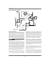
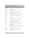
TMOD.5, TMOD.4: Timer 1 Mode Control
“Mode Select” These bit select the operating mode of the associated timer/counter as fol-
lows:
M1 M0
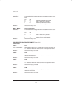
0 0 Mode 0: Eight bits with 5–bit prescale
0 1 Mode 1: 16 bits with no prescale
1 0 Mode 2: Eight bits with auto–reload
1 1 Mode 3: Timer 1 – Stopped
Initialization: Cleared to 0 on any reset.
TMOD.1, TMOD.0: Timer 0 Mode Control
“Mode Select” These bit select the operating mode of the associated timer/counter as fol-
lows:
M1 M0
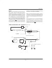
0 0 Mode 0: Eight bits with 5–bit prescale
0 1 Mode 1: 16 bits with no prescale
1 0 Mode 2: Eight bits with auto–reload
1 1 Mode 3: Timer 0 – Two 8–bit timers
Initialization: Cleared to 0 on any reset.
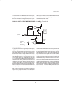
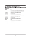
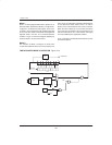
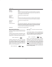
TCON REGISTER CONTROL/STATUS BITS Figure 13–2
Bit Description:
TCON.7: TF1
“Timer 1 Overflow Flag”: Status bit set to 1 when Timer 1 overflows from a previous count value of all
1’s. Cleared to 0 when CPU vectors to Timer 1 Interrupt service routine.
Initialization: Cleared to 0 on any type of reset.
TCON.6: TR1
“Timer 1 Run Control”: When set to a 1 by software, Timer 1 operation will be enabled. Timer 1 is
disabled when cleared to 0.
Initialization: Cleared to 0 on any type of reset.
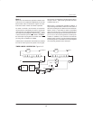
TCON.5: TF0
“Timer 0 Overflow”: Status bit set to 1 when Timer 0 overflows from a previous count value of all
1’s. Cleared to 0 when CPU vectors to Timer 0 interrupt service routine.
Initialization: Cleared to 0 on ay type of reset.
TCON.4: TR0
“Timer 0 Run Control”: When set to a 1 by a software, Timer 0 operation is enabled. Timer 0 is dis-
abled when cleared to 0.
Initialization: Cleared to 0 on any type of reset.