


USER’S GUIDE
050396 91/173
92
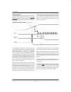
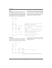
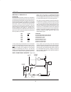
INTERRUPT ENABLE CONTROL BITS Figure 11–2
Bit Description:
All bits are read/write at any time and are cleared to 0 following any hardware reset.
IE.7: EA
“Enable All Interrupts”: When set to 1, each interrupt except for PFW may be individually enabled or
disabled by setting or clearing the associated IE.x bit. When cleared to 0,
interrupts are globally disabled and no pending interrupt request will be ac-
knowledged except for PFW.
IE.4: ES
“Enable Serial Interrupt”: When set to 1, an interrupt request from either the serial port’s TI or RI flags
can be acknowledged. Serial I/O interrupts are disabled when cleared to 0.
IE.3: ET1
“Enable Timer 1 Interrupt”: When set to 1, an interrupt request from Timer 1’s TF1 flag can be acknowl-
edged. Interrupts are disabled from this source when cleared to 0.
IE.2: EX1
“Enable External
Interrupt 1”: When set to 1, an interrupt from the IE1 flag can be acknowledged. Inter-
rupts are disabled from this source when cleared to 0.
IE.1: ET0
“Enable Timer 0 Interrupt”: When set to 1, an interrupt request from Timer 0’s TF0 flag can be acknowl-
edged. Interrupts are disabled from this source when cleared to 0.
IE.0: EX0
“Enable External
Interrupt 0”: When set to 1, an interrupt request from the IE0 flag can be acknowledged.
Interrupts are disabled from this source when cleared to 0.