


USER’S GUIDE
050396 100/173
101
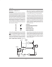
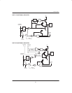
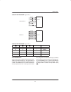
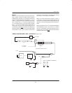
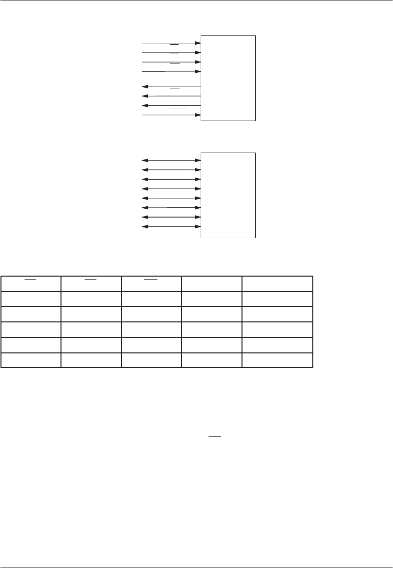
USE OF THE RPC MODE Figure 12–3
P2.3/WR
P2.2/RD
P2.1/CE
PORT 2
P2.0/A0
P2.7/DACK
P2.6/DRQ
P2.5/IBF
P2.4/OBF
CONTROL BUS
PORT 0
P0.0/D0
DATA BUS
P0.1/D1
P0.2/D2
P0.3/D3
P0.4/D4
P0.5/D5
P0.6/D6
P0.7/D7
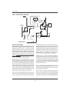
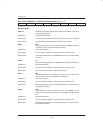
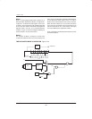
USE OF THE RPC MODE Figure 12–4
CS RD WR A0 REGISTER
0 0 1 0 DATA OUT
0 0 1 1 STATUS
0 1 0 0 DATA IN
0 1 0 1 COMMAND IN
1 X X X NO REGISTER
RPC INTERRUPTS
RPC mode provides an additional interrupt to the stan-
dard Secure Microcontroller set. An Input Buffer Full
Interrupt (IBF) will be performed (if enabled) when data
is written to the DBBIN from a host. When enabled, this
interrupt replaces the Timer 1 interrupt (vector location
1BH). Regardless of whether this interrupt is enabled,
future writes are locked out of the Secure Microproces-
sor until the DBBIN is ready. The device provides two
outputs to interrupt the host system as needed. These
are Output Buffer Full (OBF) and Input Buffer Empty
(IBF
).