


USER’S GUIDE
050396 33/173
34
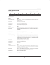
TCON.0: IT0
“Interrupt 0 Type Select”: When set to 1, 1–to–0 transitions on INT0 will be used to generate interrupt
requests from this pin. When cleared to 0, INT0
is level–activated.
Initialization: Cleared to a 0 on any type of reset.
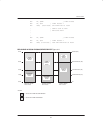
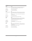
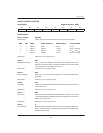
TIMER MODE REGISTER
Label: TMOD Register Address: 089H
D7 D6 D5 D4 D3 D2 D1 D0
GATE C/T M1 M0 GATE C/T M1 M0
Bit Description:
TMOD.7 (Timer 1);
TMOD.3 (Timer 0): GATE
“Gate Control”: When set to 1 with TRn=1, timer/counter’s input count pulses will only be
delivered while a 1 is present on the INT
pin. When cleared to 0, count
pulses will always be received by the timer/counter a long as TRn=1.
Initialization: Cleared to 0 on any reset.
TMOD.6 (Timer 1);
TMOD.2 (Timer 0) C/T
“Counter/Timer Select”: When set to 1, the counter function is selected for the associated timer;
when cleared to 0, the timer function is selected.
Initialization: Cleared to 0 on any reset.
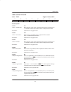
TMOD.5, TMOD.4 (Timer 1);
TMOD.1, TMOD.0 (Timer 0): M1,M0
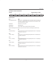
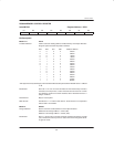
“Mode Select”: These bits select the operating mode of the associated timer/counter as fol-
lows:
M1 M0
0 0 Mode 0: 8 bits with 5–bit prescale
0 1 Mode 1: 16 bits with no prescale
1 0 Mode 2: 8 bits with auto–reload
1 1 Mode 3: Timer 0 – Two 8–bit timers
Timer 1 – Stopped
Initialization: Cleared to 0 on any reset.