


USER’S GUIDE
050396 34/173
35
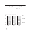
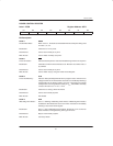
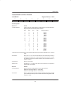
SERIAL CONTROL REGISTER
Label:SCON Register Address: 098H
D7 D6 D5 D4 D3 D2 D1 D0
SM0 SM1 SM2 REN TB8 RB8 TI RI
Bit Description:
SCON.7, SCON.6: SM0, SM1
“Mode Select”: Used to select the operational mode of the serial I/O port as follows:
SM0 SM1 MODE WORD FUNCTION BAUD LENGTH CLOCK PERIOD
0 0 Mode 0 SYNC 8–bits 12 t
CLK
0 1 Mode 1 ASYNC 10–bits Timer 1 Overflow
1 0 Mode 2 ASYNC 11–bits 64 t
CLK
or 32 t
CLK
1 1 Mode 3 ASYNC 11–bits Timer 1 Overflow
Initialization: Cleared to 0 on any type of reset.
SCON.5: SM2
“Multiple MCU Comm”: Used to enable the multiple microcontroller communications feature for
modes 2 and 3. When SM2=1, RI will be activated only when serial words
are received which cause RB8 to be set to a 1.
Initialization: Cleared to a 0 on any type of reset.
SCON.4: REN
“Receive Enable”: When set to 1, the receive shift register will be enabled. Disabled when
cleared to 0.
Initialization: Cleared to a 0 on any type of reset.
SCON.3: TB8
“Xmit Bit 8”: Can be set or cleared to define the state of the 9th data bit in modes 2 and 3 of
a serial data word.
Initialization: Cleared to a 0 on any type of reset.
SCON.2: RB8
“Rec. Bit 8”: Indicates the state of the 9th data bit received while in modes, 2 or 3. If mode
1 is selected with SM2=0, RB8 is the state of the stop bit which was received.
RB8 is not used in mode 0.
Initialization: Cleared to a 0 on any type of reset.
SCON.1: TI
“Xmit Interrupt”: Status bit used to signal that a data word has been completely shifted out. In
mode 0, it is set at the end of the 8th data bit. Set when the stop bit is trans-
mitted in all other modes.