


USER’S GUIDE
050396 132/173
133
SERIAL PROGRAM LOAD MODE
The Serial Bootstrap Loader provides the easiest meth-
od of initially loading application software into the non-
volatile RAM. Communication can be performed over a
standard asynchronous serial communications port us-
ing a terminal emulator program with 8–N–1 (8 data bits,
no parity, 1 stop bit) protocol settings. A typical applica-
tion would use a simple RS232C serial interface to pro-
gram the device as part of a final production procedure.
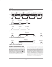
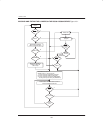
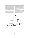
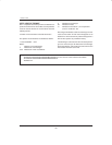
The hardware configuration which is required for the Se-
rial Program Load mode is illustrated in Figure 16–2.
Note that as shown, it is important to have P2.7 and P2.6
either open or pulled up during serial programming of a
DS5000 series device. Failure to do this results in a par-
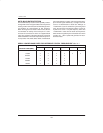
allel load operation. A variety of crystals can be used to
produce standard baud rates. Tables 16–1 and 16–2
show the baud rates which are supported using a variety
of popular crystal frequencies. The serial loader is
designed to operate across a 3–wire interface from a
standard UART. The receive, transmit, and ground
wires are all that are necessary to establish commu-
nication with the device.
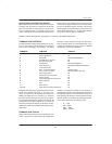
The Serial Loader implements an easy–to–use com-
mand line interface which allows an application program
in an Intel Hex representation to be loaded and read
back from the device. Intel Hex is the typical format
which existing 8051 cross–assemblers output.
SERIAL LOAD CONFIGURATION Figure 16–2
PSEN
RST
+5V
1K
10K
RS232C
11.059 MHz
7.3728 MHz
1.8432 MHz
DS1228
V
CC
GND
Soft Micro
P2.7
P2.6
TXD
RXD
XTAL1
XTAL2
P1.7–
P2.4–
01.0
P2.0
P0.7–
P0.0
P3.7–
P3.2
PROGRAM
RUN
OPEN OR
PULLED UP