


USER’S GUIDE
050396 41/173
42
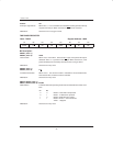
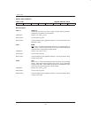
PROGRAM STATUS WORD REGISTER
Label:PSW Register Address: 0D0H
D7 D6 D5 D4 D3 D2 D1 D0
C AC F0 RS1 RS0 OV P
All of the bits in PSW except parity are read/write and are cleared to 0 on any type of reset. The Parity bit is read only
and is cleared to 0 on any type of reset.
Bit Description:
PSW.7: C
“Carry”: Set when the previous operation resulted in a carry (during addition) or a
borrow (during subtraction). Otherwise cleared.
PSW.6: AC
“Auxiliary-Carry”: Set when the previous operation resulted in a carry (during addition) or a
borrow (during subtraction) from the low–order nibble. Otherwise cleared.
PSW.5: F0
“User Flag 0”: General–purpose flag bit which can be set or cleared as needed.
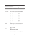
PSW.4–3: R1–R0
“Register Bank Select”: Used to select an 8–byte bank of registers within the Data Register space to
be assigned as R0–R8 in subsequent instructions. The 8–byte bank starting
address selection is as follows:
R1 R0 Data Register Address (R0)
0 0 00H
0 1 08H
1 0 10H
1 1 18H
PSW.2: OV
“Overflow”: Set when a carry was generated into the high–order bit but not a carry out of
the high–order bit as a result of the previous operation, and visa–versa. OV
is normally used in 2’s complement arithmetic.
PSW.0: P
“Parity”: Set if the modulo–2 sum of the eight bits of the accumulator is 1 (odd parity);
cleared on even parity.