


Introduction
Product Descriptions
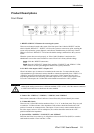
Front Panel
1: RESET & DEFAULT buttons for restoring the system
There are two buttons located at the center of the front panel. One is labeled “RESET” and the
other is labeled “DEFAULT.” “RESET” will force the system to restart at any point, meaning the
system will perform the system diagnosis, and software installation may be necessary if the IP
address is not fixed. “DEFAULT” will restore the default settings, and then force the system to
restart.
When the system does not work properly, or VPort 2140’s IP address is not known, the
administrator can use the restore function to restore VPort 2140’s factory default settings.
Step1: Click the “RESET” button once.
Step2: Press the “DEFAULT” button firmly until the “CONNECT” and “SERIAL” LEDs
flash 2 times to run the system diagnosis and erase the system parameters.
2 & 3: BNC video outputs “OUT” & inputs “IN”
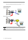
VPort 2140 allows up to 4 cameras to be attached at the same time. To ensure that the correct
video modulation type is detected, cameras should be connected sequentially from “VIDEO 1” to
“VIDEO 4” and powered on before the VPort is powered on. Video outputs also have four
loop-through connectors for connecting with other capture devices, such as a time-lapsed VCR.
To use the video outputs, the 75 Ohm DIP switch should be turned to the “OFF” position.
Although the analog cameras have 2 different standards, NTSC or PAL, all of the cameras connected
to VPort 2140 Video Server should use the same standard.
4: Camera ID: “VIDEO 1,” “VIDEO 2,” “VIDEO 3,”and “VIDEO 4”
Each camera connected to VPort 2140 has a Camera ID used by VPort to identify the camera.
5: 75 Ohm DIP Switch
There are four 75 Ohm DIP switches numbered from “1” to “4” on the front panel. They are used
to enable the 75-Ohm resistance video impedance. DIP switches should be turned to the “ON”
position if cameras are connected to the video inputs. If users want to connect another device to
the video output, such as a VCR or multiplexer, the switches should be turned to the “OFF”
position to disable the impedance.
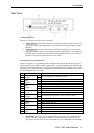
6: System LEDs: “POWER,” “CONNECT,” and “SERIAL”
Each time the Video Server starts up, it will perform a Power-On-Self-Test (POST) to examine
each hardware module. VPort 2140 has 3 LEDs:
VPort 2140 User’s Manual
1-5