


range between 12V and 15V. Polarity does not matter if you use AC. The DC output
through Pin 1 and Pin 2 is fed from the power adaptor of the Video Server or pin 11 and
pin 12 if an external power source is attached. The current of external devices is limited to
less than 500 mA.
b. COM 1 RS-485: If the device connected to the COM1 port has an RS-485 interface, such
as a PTZ camera control, wire the RS-485 Data+ and Data- control lines to COM RS-485
pin “+” and pin “ –”. If the distance from the controlled device is too long to allow
accurate function, an external power source may be used to pull the RS-485 signal to
“high” status.
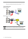
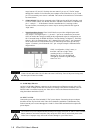
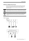
c. Digital Input/Relay Output: VPort 2140 Video Server provides 4 digital inputs and 2
relay outputs. The Digital Input’s “+” pin and “-” pin can be connected to an external
sensor to monitor the voltage according to the programmed scripts in configuration (see
the “Command Script for DI/DO & Camera’s Actions Setting” in Chapter 5). The Relay
Output’s “NO” pin (Normal Open), “NC” (Normal Close) pin, and “C” pin (Common)
can be used to turn an external alarm on or off. When the system starts up, both relay
outputs’ “Common” pin will short the “NC” pin. A simple example is illustrated in the
diagram below.
If DI1 is configured to “rising” status, so
that DO1 is driven to “high” status
(resulting in DO1’s “Common” pin
shorting the “NO” pin), the light bulb
will light up when DI1’s signal changes
from 0V to 12V.
COM 1 RS-485 and COM 1 RS-232 share the same UART chip. If one of the ports is being used,
the other port will not be available.
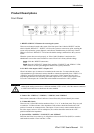
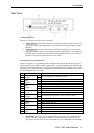
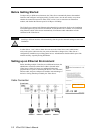
11: 10/100 Mbps Ethernet
An RJ45 10/100 Mbps Ethernet connector can be connected to an Ethernet network with a UTP
category 5 cable of length shorter than 100 meters (according to the Ethernet standard). Once the
Ethernet cable is connected correctly, the Video Server will use the Ethernet interface before
using the modem attached to COM 2.
12: INPUT 12 VDC
Connect the power jack of the included 12 VDC power adaptor. Connecting the power adaptor
should be the last step involved in the Video Server hardware installation. Administrators may
feed an external power source through pins 11 and 12 of the GPIO terminal block to replace the
power adapter.
The Video Server power adaptor and the external power supply (from pins 11 and 12 of the Terminal
Block) cannot be used at the same time. Only one power source can be used to feed power to the
Video Server. Improper usage will result in serious damage to your Video Server.
VPort 2140 User’s Manual
1-8