MultiModemISI Hybrid Series, ISIHI-2S 163
Appendix
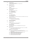
COMMAND DESCRIPTION
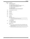
>D
n
Embedded Protocol Analyzer
n
= 0, 1, 2, 3, 4, 98, or 99
>D0
Display B-channel traffic, decoded as V.120
>D1
Display D-channel traffic, decoding layers 2 and 3 (Q.921 and Q.931)
>D2
Display D-channel traffic, decoding layer 2 only (Q.921)
>D3
Display D-channel traffic, decoding layer 3 only (Q.931)
>D4
Display B-channel traffic, decoded as X.75
>D5
Display async PPP data
>D6
Display sync PPP data
>D98
Disable Embedded Protocol Analyzer, buffered data unchanged
>D99
Enable Embedded Protocol Analyzer, clearing buffered data
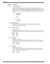
#X
n
Send Single/Multiple Xoff Characters
&C
n
DCD Control
&D
n
DTR Control
&E
n
Flow Control
&F
n
Factory Profiles
&R CTS Control
&S
n
DSR Control
n
= 0, 1, or 2
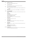
&S0
DSR is always high.
&S1
DSR acts normally (follows state of CD signal—goes high when the ISIHI-2S detects a
carrier signal and goes low when carrier signal is lost)
&S2
DSR always high except on disconnect when it drops for period of time set by S10; then
goes high again
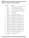
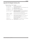
&V
n
View Port Parameters
n
=0 Display port 0 parameters
n
=1 Display port 1 parameters
n
=2 Display port 2 parameters
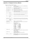
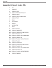
&W
n
Store Active Profile
n
= 0 or 1
&W0 Stores all current AT command and S-register values in nonvolatile random access
memory (NVRAM) and configures TA to read custom settings in NVRAM when modem
turned on or when reset with
Z
command. (
&F
reset command continues to read factory
default settings in ROM.)
&W1
Erases your custom settings in NVRAM the next time the TA is turned off or reset, causing
the TA to read the factory default settings in ROM whenever it is turned on or reset.


