


Chapter 8 PFI
NI 6238/6239 User Manual 8-4 ni.com
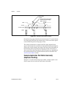
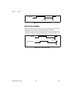
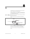
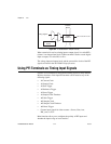
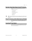
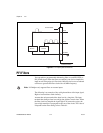
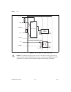
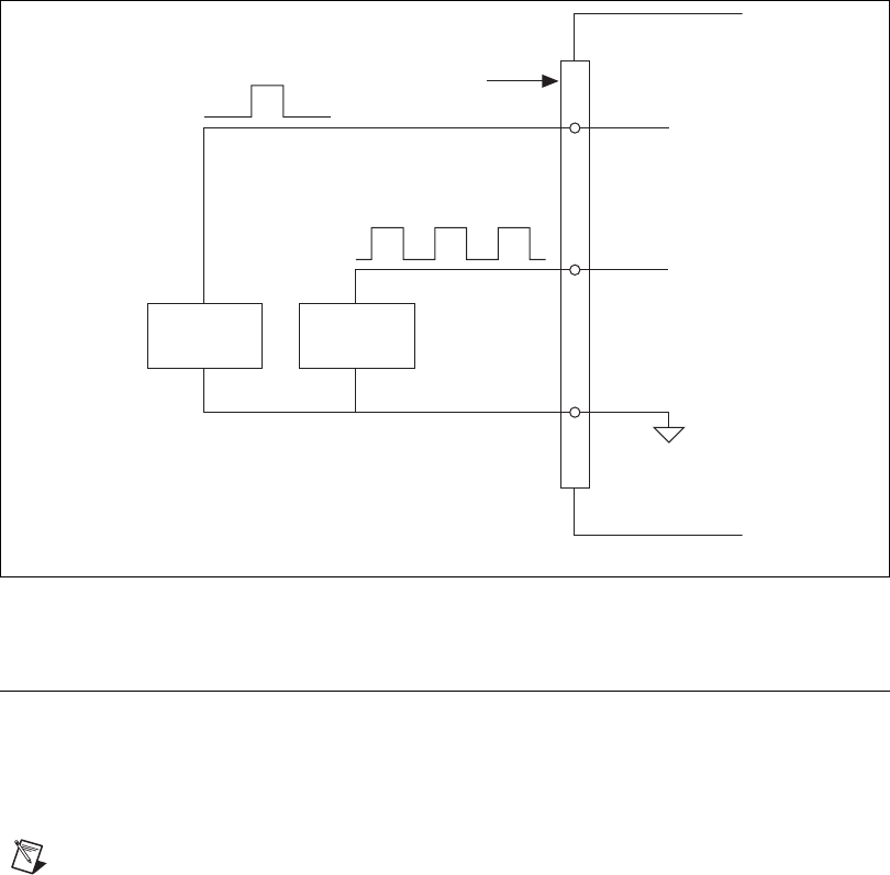
Figure 8-3. PFI Input Signals Connections
PFI Filters
You can enable a programmable debouncing filter on each PFI, RTSI, or
PXI_STAR signal. When the filters are enabled, your device samples the
input on each rising edge of a filter clock. M Series devices use an onboard
oscillator to generate the filter clock with a 40 MHz frequency.
Note NI-DAQmx only supports filters on counter inputs.
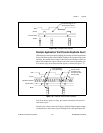
The following is an example of low-to-high transitions of the input signal.
High-to-low transitions work similarly.
Assume that an input terminal has been low for a long time. The input
terminal then changes from low-to-high, but glitches several times. When
the filter clock has sampled the signal high on N consecutive edges, the
low-to-high transition is propagated to the rest of the circuit. The value of
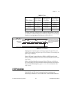
N depends on the filter setting; refer to Table 8-1.
PFI 0
Source
PFI 2
Source
M Series Device
P0.GND
PFI 2
PFI 0
I/O Connector