


Chapter 4 Analog Input
NI 6238/6239 User Manual 4-12 ni.com
mainly to AI signal routing to the device, although they also apply to signal
routing in general.
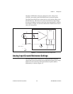
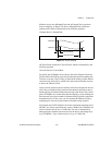
Minimize noise pickup and maximize measurement accuracy by using
individually shielded, twisted-pair wires to connect AI signals to the
device. With this type of wire, the signals attached to the positive and
negative input channels are twisted together and then covered with a shield.
You then connect this shield only at one point to the signal source ground.
This kind of connection is required for signals traveling through areas with
large magnetic fields or high electromagnetic interference.
Refer to the NI Developer Zone document, Field Wiring and Noise
Considerations for Analog Signals, for more information. To access this
document, go to
ni.com/info and enter the info code rdfwn3.
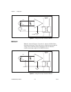
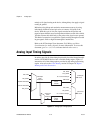
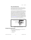
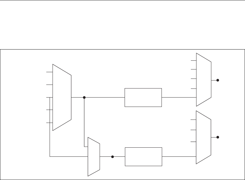
Analog Input Timing Signals
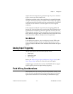
In order to provide all of the timing functionality described throughout this
section, NI 6238/6239 devices have a flexible timing engine. Figure 4-7
summarizes all of the timing options provided by the analog input timing
engine. Also refer to the Clock Routing section of Chapter 10, Digital
Routing and Clock Generation.
Figure 4-7. Analog Input Timing Options
PFI, RTSI
PXI_STAR
20 MHz Timebase
100 kHz Timebase
PXI_CLK10
Programmable
Clock
Divider
ai/Sample
Clock
Timebase
ai/Convert
Clock
Timebase
PFI, RTSI
PXI_STAR
Ctr
n
Internal Output
SW Pulse
PFI, RTSI
PXI_STAR
Ctr
n
Internal Output
ai/Convert
Clock
ai/Sample
Clock
Programmable
Clock
Divider