


© National Instruments Corporation 3-1 NI 6238/6239 User Manual
3
Connector Information
The I/O Connector Signal Descriptions and RTSI Connector Pinout
sections contain information on M Series connectors. Refer to
Appendix A, Device-Specific Information, for device I/O connector
pinouts.
I/O Connector Signal Descriptions
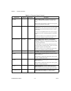
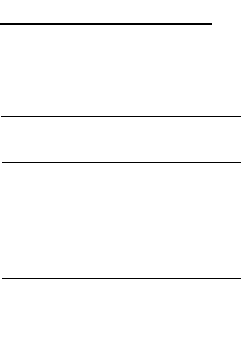
Table 3-1 describes the signals found on the I/O connectors. Not all signals
are available on all devices.
Table 3-1. I/O Connector Signals
Signal Name Reference Direction Description
AI GND — — Analog Input Ground—These terminals are the input bias
current return point. AI GND and AO GND are connected on
the device.
Note: AI GND and AO GND are isolated from earth ground,
chassis ground, P0.GND, and P1.GND.
AI <0..7>± AI GND Input Analog Input Channels 0 to 7±—AI 0+ and AI 0– are the
positive and negative inputs of differential analog input
channel 0. Similarly, the following signal pairs also form
differential input channels:
<AI 1+, AI 1–>, <AI 2+, AI 2–>, <AI 3+, AI 3–>,
<AI 4+, AI 4–>, <AI 5+, AI 5–>, <AI 6+, AI 6–>,
<AI 7+, AI 7–>
Also refer to the Analog Input Ground-Reference Settings
section of Chapter 4, Analog Input.
Note: AI <0..7>± are isolated from earth ground and chassis
ground.
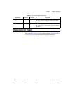
AO <0..1> AO GND Output Analog Output Channels 0 to 1—These terminals supply the
current output of AO channels 0 to 1.
Note: AO <0..1> are isolated from earth ground and chassis
ground.