


Chapter 10 Digital Routing and Clock Generation
NI 6238/6239 User Manual 10-4 ni.com
• Share trigger signals between devices
Many National Instruments DAQ, motion, vision, and CAN devices
support RTSI.
In a PCI system, the RTSI bus consists of the RTSI bus interface and a
ribbon cable. The bus can route timing and trigger signals between several
functions on as many as five DAQ, vision, motion, or CAN devices in the
computer. In a PXI system, the RTSI bus consists of the RTSI bus interface
and the PXI trigger signals on the PXI backplane. This bus can route timing
and trigger signals between several functions on as many as seven DAQ
devices in the system.
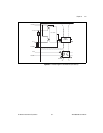
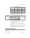
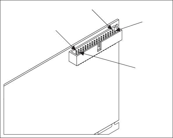
RTSI Connector Pinout
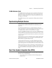
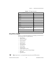
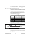
Figure 10-2 shows the RTSI connector pinout and Table 10-1 describes the
RTSI signals. The RTSI signals are referenced to earth/chassis ground; they
are not isolated.
Figure 10-2. NI 6238/6239 RTSI Pinout
Terminal 2
Terminal 34
Terminal 33
Terminal 1