


Chapter 8 PFI
NI 6238/6239 User Manual 8-6 ni.com
Consult the device specifications for details. However, you should avoid
these fault conditions by following these guidelines.
•Do not connect any digital output line to any external signal source,
ground signal, or power supply.
• Understand the current requirements of the load connected to the
digital output lines. Do not exceed the specified current output limits
of the digital outputs. NI has several signal conditioning solutions for
digital applications requiring high current drive.
•Do not drive the digital input lines with voltages or current outside of
its normal operating range.
• Treat the DAQ device as you would treat any static sensitive device.
Always properly ground yourself and the equipment when handling the
DAQ device or connecting to it.
Programmable Power-Up States
By default, the digital output lines (P1.<0..3>/PFI <6..9>) are set to 0. They
can be programmed to power up as 0 or 1.
Refer to the NI-DAQmx Help or the LabVIEW 8.x Help for more
information about setting power-up states in NI-DAQmx or MAX.
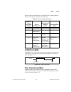
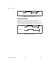
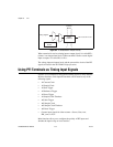
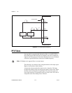
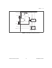
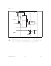
Connecting Digital I/O Signals
The DI signals P0.<0..5> are referenced to P0.GND and DO signals
P1.<0..3> are referenced to P1.GND.
Figures 8-5 and 8-6 show P0.<0..5> and P1.<0..3> on the NI 6238 and the
NI 6239 device, respectively. Digital input and output signals can range
from 0 to 30 V. Refer to the NI 6238/6239 Specifications for more
information.