


Chapter 10 Digital Routing and Clock Generation
NI 6238/6239 User Manual 10-6 ni.com
Using RTSI Terminals as Timing Input Signals
You can use RTSI terminals to route external timing signals to many
different M Series functions. Each RTSI terminal can be routed to any of
the following signals.
• AI Convert Clock
• AI Sample Clock
• AI Start Trigger
• AI Reference Trigger
• AI Pause Trigger
• AI Sample Clock Timebase
•AO Start Trigger
• AO Sample Clock
• AO Sample Clock Timebase
• AO Pause Trigger
• Counter input signals for either counter—Source, Gate, Aux,
HW_Arm, A, B, or Z
Most functions allow you to configure the polarity of PFI inputs and
whether the input is edge or level sensitive.
RTSI Filters
You can enable a programmable debouncing filter on each PFI, RTSI, or
PXI_STAR signal. When the filters are enabled, your device samples the
input on each rising edge of a filter clock. M Series devices use an onboard
oscillator to generate the filter clock with a 40 MHz frequency.
Note NI-DAQmx only supports filters on counter inputs.
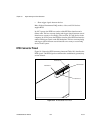
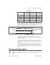
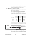
The following is an example of low-to-high transitions of the input signal.
High-to-low transitions work similarly.
Assume that an input terminal has been low for a long time. The input
terminal then changes from low-to-high, but glitches several times. When
the filter clock has sampled the signal high on N consecutive edges, the
low-to-high transition is propagated to the rest of the circuit. The value of
N depends on the filter setting; refer to Table 10-2.