


Chapter 4 Analog Input
NI 6238/6239 User Manual 4-18 ni.com
•RTSI <0..7>
• Input PFI <0..5>
•PXI_STAR
ai/SampleClockTimebase is not available as an output on the I/O connector.
ai/SampleClockTimebase is divided down to provide one of the possible
sources for ai/SampleClock. You can configure the polarity selection for
ai/SampleClockTimebase as either rising or falling edge.
AI Convert Clock Signal
Caution Setting the conversion rate higher than the maximum rate specified for your
device will result in errors.
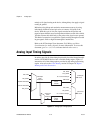
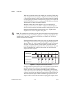
Use the AI Convert Clock (ai/ConvertClock) signal to initiate a single A/D
conversion on a single channel. A sample, controlled by the AI Sample
Clock, consists of one or more conversions.
You can specify either an internal or external signal as the source of
ai/ConvertClock. You also can specify whether the measurement sample
begins on the rising edge or falling edge of ai/ConvertClock.
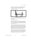
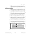
With NI-DAQmx, the driver will choose the fastest conversion rate possible
based on the speed of the A/D converter and add 10 µs of padding between
each channel to allow for adequate settling time. This scheme enables the
channels to approximate simultaneous sampling and still allow for
adequate settling time. If the AI Sample Clock rate is too fast to allow for
this 10 µs of padding, NI-DAQmx will choose the conversion rate so that
the AI Convert Clock pulses are evenly spaced throughout the sample.
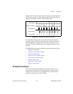
To explicitly specify the conversion rate, use the AI Convert Clock Rate
DAQmx Timing property node or function.
Using an Internal Source
One of the following internal signals can drive ai/ConvertClock:
• AI Convert Clock Timebase (divided down)
• Counter n Internal Output
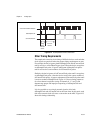
A programmable internal counter divides down the AI Convert Clock
Timebase to generate ai/ConvertClock. The counter is started by
ai/SampleClock and continues to count down to zero, produces an
ai/ConvertClock, reloads itself, and repeats the process until the sample is