


Chapter 10 Digital Routing and Clock Generation
© National Instruments Corporation 10-7 NI 6238/6239 User Manual
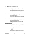
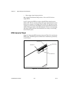
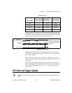
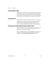
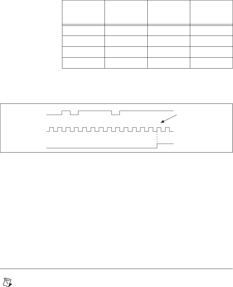
The filter setting for each input can be configured independently. On power
up, the filters are disabled. Figure 10-3 shows an example of a low-to-high
transition on an input that has its filter set to 125 ns (N = 5).
Figure 10-3. Filter Example
Enabling filters introduces jitter on the input signal. For the 125 ns and
6.425 µs filter settings, the jitter is up to 25 ns. On the 2.55 ms setting, the
jitter is up to 10.025 µs.
When a PFI input is routed directly to RTSI, or a RTSI input is routed
directly to PFI, the M Series device does not use the filtered version of the
input signal.
Refer to the KnowledgeBase document, Digital Filtering with M Series
and CompactDAQ, for more information about digital filters and counters.
To access this KnowledgeBase, go to
ni.com/info and enter the info
code
rddfms.
PXI Clock and Trigger Signals
Note PXI clock and trigger signals are only available on PXI devices. Other devices use
RTSI.
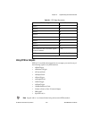
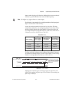
Table 10-2. Filters
Filter Setting
N (Filter
Clocks Needed
to Pass Signal)
Pulse Width
Guaranteed to
Pass Filter
Pulse Width
Guaranteed to
Not Pass Filter
125 ns 5 125 ns 100 ns
6.425 µs 257 6.425 µs 6.400 µs
2.55 ms ~101,800 2.55 ms 2.54 ms
Disabled — — —
1231 4 12345
RTSI, PFI, or
PXI_STAR Terminal
Filter Clock
(40 MHz)
Filtered Input
Filtered input goes high
when terminal is sampled
high on five consecutive
filter clocks.