


Chapter 9 Isolation and Digital Isolators
NI 6238/6239 User Manual 9-2 ni.com
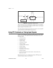
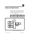
The non-isolated ground is connected to the chassis ground of the PC or
chassis where the device is installed.
Each isolated ground is not connected to the chassis ground of the PC or
chassis. The isolated ground can be at a higher or lower voltage relative to
the non-isolated ground. All analog measurements are made relative to its
isolated ground signal.
Each isolated ground is an input to the NI 6238/6239 device. The user must
connect this ground to the ground of system being measured or controlled.
Refer to the Connecting Analog Current Input Signals section of Chapter 4,
Analog Input, the Connecting Analog Current Output Signals section of
Chapter 5, Analog Output, the Connecting Digital I/O Signals section of
Chapter 6, Digital Input and Output, and the Connecting PFI Input Signals
section of Chapter 8, PFI, for more information.
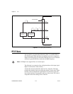
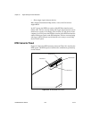
Digital Isolation
The NI 6238/6239 uses digital isolators. Unlike analog isolators, digital
isolators do not introduce any analog error in the measurements taken by
the device. The A/D converter, used for analog input, is on the isolated side
of the device. The analog inputs are digitized before they are sent across the
isolation barrier. Similarly, the D/A converters, used for analog output, are
on the isolated side of the device.
Benefits of an Isolated DAQ Device
With isolation, engineers can safely measure a small current in the presence
of a large common-mode voltage signal. Some advantages of isolation are
as follows:
• Improved rejection—Isolation increases the ability of the
measurement system to reject common-mode voltages when the
common-mode voltage is applied to the isolated ground.
Common-mode voltage is the signal that is present or “common” to
both the positive and negative input of a measurement device, but is not
part of the signal to be measured.
• Improved accuracy—Isolation improves measurement accuracy by
physically preventing ground loops. Ground loops, a common source
of error and noise, are the result of a measurement system having
multiple grounds at different potentials.