


Chapter 7 Counters
© National Instruments Corporation 7-23 NI 6238/6239 User Manual
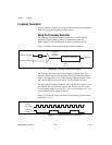
Pulse Train Generation
Continuous Pulse Train Generation
This function generates a train of pulses with programmable frequency and
duty cycle. The pulses appear on the Counter n Internal Output signal of the
counter.
You can specify a delay from when the counter is armed to the beginning
of the pulse train. The delay is measured in terms of a number of active
edges of the Source input.
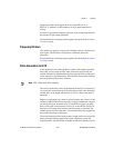
You specify the high and low pulse widths of the output signal. The pulse
widths are also measured in terms of a number of active edges of the Source
input. You also can specify the active edge of the Source input (rising or
falling).
The counter can begin the pulse train generation as soon as the counter is
armed, or in response to a hardware Start Trigger. You can route the Start
Trigger to the Gate input of the counter.
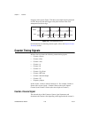
You also can use the Gate input of the counter as a Pause Trigger (if it is not
used as a Start Trigger). The counter pauses pulse generation when the
Pause Trigger is active.
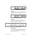
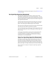
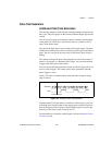
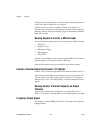
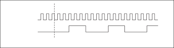
Figure 7-25 shows a continuous pulse train generation (using the rising
edge of Source).
Figure 7-25. Continuous Pulse Train Generation
Continuous pulse train generation is sometimes called frequency division.
If the high and low pulse widths of the output signal are M and N periods,
then the frequency of the Counter n Internal Output signal is equal to the
frequency of the Source input divided by M + N.
For information on connecting counter signals, refer to the Default Counter
Terminals section.
SOURCE
OUT
Counter Armed