


Chapter 4 Analog Input
© National Instruments Corporation 4-3 NI 6238/6239 User Manual
M Series devices use a calibration method that requires some codes
(typically about 5% of the codes) to lie outside of the specified range. This
calibration method improves absolute accuracy, but it increases the nominal
resolution of input ranges by about 5% over what the formulas shown above
would indicate.
Choose an input range that matches the expected input range of your signal.
A large input range can accommodate a large signal variation, but reduces
the measurement resolution. Choosing a smaller input range improves the
measurement resolution, but may result in the input signal going out of
range.
For more information on programming these settings, refer to the
NI-DAQmx Help or the LabVIEW 8.x Help.
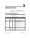
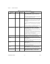
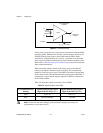
Table 4-1 shows the input ranges and resolutions supported by the NI 6238
and NI 6239 devices.
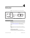
Connecting Analog Current Input Signals
When making signal connections, caution must be taken with the voltage
level of the signal going into the device. There are two types of connections
that can be made.
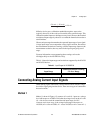
Method 1
Method 1, shown in Figure 4-2, connects AI + and AI – inputs at a voltage
level with respect to AI GND. Verify that the voltage levels on the AI + and
AI – side do not exceed the common-mode input range of ±10 V.
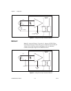
Common-mode input range is the voltage input range with respect to
AI GND (AI + versus AI GND, AI – versus AI GND, or AI + versus AI –).
Table 4-1. Input Ranges for NI 6238/6239
Input Range
Nominal Resolution Assuming
5% Over Range
20 mA 640 nA
(20 mA – (–20 mA))
2
16
= 610 nA