


Chapter 7 Counters
© National Instruments Corporation 7-33 NI 6238/6239 User Manual
Other Counter Features
Cascading Counters
You can internally route the Counter n Internal Output and Counter n TC
signal of each counter to the Gate inputs of the other counter. By cascading
two counters together, you can effectively create a 64-bit counter. By
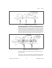
cascading counters, you also can enable other applications. For example, to
improve the accuracy of frequency measurements, use reciprocal frequency
measurement, as described in the Method 3—Measure Large Range of
Frequencies Using Two Counters section.
Counter Filters
You can enable a programmable debouncing filter on each PFI, RTSI, or
PXI_STAR signal. When the filters are enabled, your device samples the
input on each rising edge of a filter clock. M Series devices use an onboard
oscillator to generate the filter clock with a 40 MHz frequency.
Note NI-DAQmx only supports filters on counter inputs.
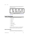
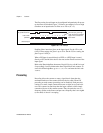
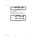
The following is an example of low-to-high transitions of the input signal.
High-to-low transitions work similarly.
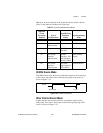
Assume that an input terminal has been low for a long time. The input
terminal then changes from low-to-high, but glitches several times. When
the filter clock has sampled the signal high on N consecutive edges, the
low-to-high transition is propagated to the rest of the circuit. The value of
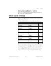
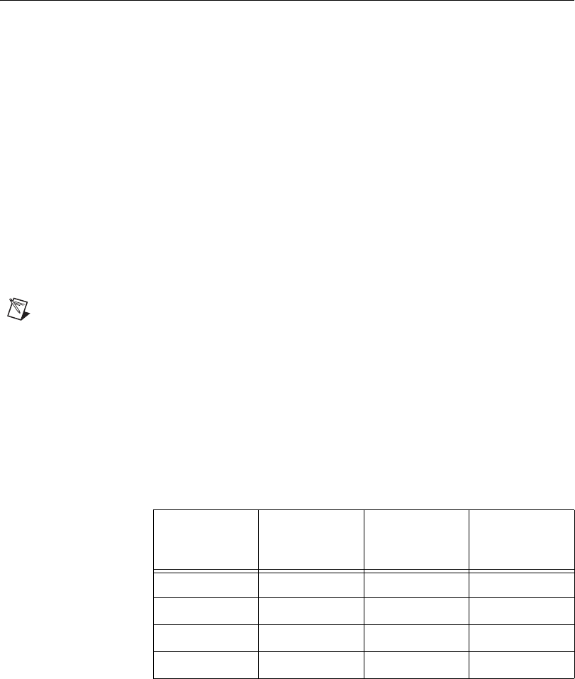
N depends on the filter setting; refer to Table 7-5.
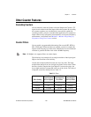
Table 7-5. Filters
Filter Setting
N (Filter
Clocks Needed
to Pass Signal)
Pulse Width
Guaranteed to
Pass Filter
Pulse Width
Guaranteed to
Not Pass Filter
125 ns 5 125 ns 100 ns
6.425 µs 257 6.425 µs 6.400 µs
2.55 ms ~101,800 2.55 ms 2.54 ms
Disabled — — —