


Chapter 7 Counters
NI 6238/6239 User Manual 7-26 ni.com
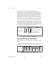
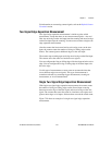
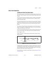
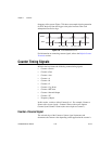
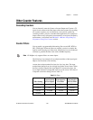
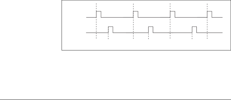
frequency of the system. Figure 7-28 shows an example of pulse generation
for ETS; the delay from the trigger to the pulse increases after each
subsequent Gate active edge.
Figure 7-28. Pulse Generation for ETS
For information on connecting counter signals, refer to the Default Counter
Terminals section.
Counter Timing Signals
M Series devices feature the following counter timing signals.
• Counter n Source
• Counter n Gate
• Counter n Aux
• Counter n A
• Counter n B
• Counter n Z
• Counter n Up_Down
• Counter n HW Arm
• Counter n Internal Output
• Counter n TC
•Frequency Output
In this section, n refers to either Counter 0 or 1. For example, Counter n
Source refers to two signals—Counter 0 Source (the source input to
Counter 0) and Counter 1 Source (the source input to Counter 1).
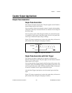
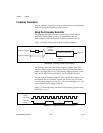
Counter n Source Signal
The selected edge of the Counter n Source signal increments and
decrements the counter value depending on the application the counter is
OUT
D1 D2 = D1 + ΔDD3 = D1 + 2ΔD
GATE