


Appendix A Specifications for AT-MIO-16E-1, AT-MIO-16E-2, and AT-MIO-64E-3
© National Instruments Corporation A-7 AT E Series User Manual
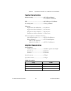
Voltage Output
Ranges.................................................... ±10 V, 0 to 10 V, ±EXTREF,
0toEXTREF
(software selectable)
Output coupling...................................... DC
Output impedance .................................. 0.1 Ω max
Current drive .......................................... ±5 mA max
Protection ............................................... Short-circuit to ground
Power-on state........................................ 0 V (±200 mV)
External reference input
Range .............................................. ±11 V
Overvoltage protection ................... ±25 V powered on,
±15Vpoweredoff
Input impedance.............................. 10 kΩ
Bandwidth (–3 dB).......................... 1 MHz
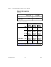
Dynamic Characteristics
Settling time for full-scale step .............. 3 µs to ±0.5 LSB accuracy
Slew rate................................................. 20 V/µs
Noise ...................................................... 200 µV
rms
,DCto1MHz
Glitch energy (at midscale transition)
Magnitude
Reglitching disabled ................ ±200 mV
Reglitching enabled ................. ±30 mV
Duration .......................................... 1.5 µs
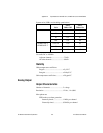
Stability
Offset temperature coefficient ............... ±50 µV/°C
Gain temperature coefficient
Internal reference ............................ ±25 ppm/°C
External reference........................... ±25 ppm/°C