


Chapter 4 Connecting Signals
AT E Series User Manual 4-36 ni.com
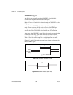
STARTSCAN Signal
Any PFI pin can externally input the STARTSCAN signal, which is
available as an output on the PFI7/STARTSCAN pin.
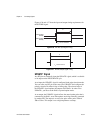
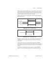
Refer to Figures 4-13 and 4-14 for the relationship of STARTSCAN to the
DAQ sequence.
As an input, the STARTSCAN signal is configured in the edge-detection
mode. You can select any PFI pin as the source for STARTSCAN and
configure the polarity selection for either rising or falling edge. The
selected edge of the STARTSCAN signal initiates a scan. The sample
interval counter is started if you select internally triggered CONVERT*.
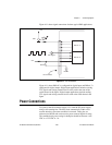
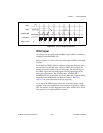
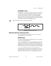
As an output, the STARTSCAN signal reflects the actual start pulse that
initiates a scan, even if the starts are being externally triggered by another
PFI. You have two output options. The first is an active high pulse with a
pulse width of 50 to 100 ns, which indicates the start of the scan. The
second action is an active high pulse that terminates at the start of the last
conversion in the scan, which indicates a scan in progress. STARTSCAN is
deserted t
off
after the last conversion in the scan is initiated. This output is
set to high-impedance at startup.
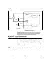
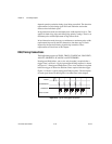
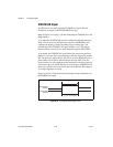
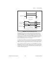
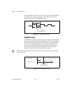
Figures 4-19 and 4-20 show the input and output timing requirements for
the STARTSCAN signal.
Figure 4-19. STARTSCAN Input Signal Timing
Rising-Edge
Polarity
Falling-Edge
Polarity
t
w
= 10 ns minimum
t
w