


Chapter 4 Connecting Signals
© National Instruments Corporation 4-29 AT E Series User Manual
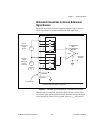
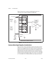
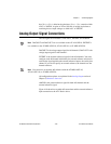
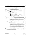
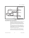
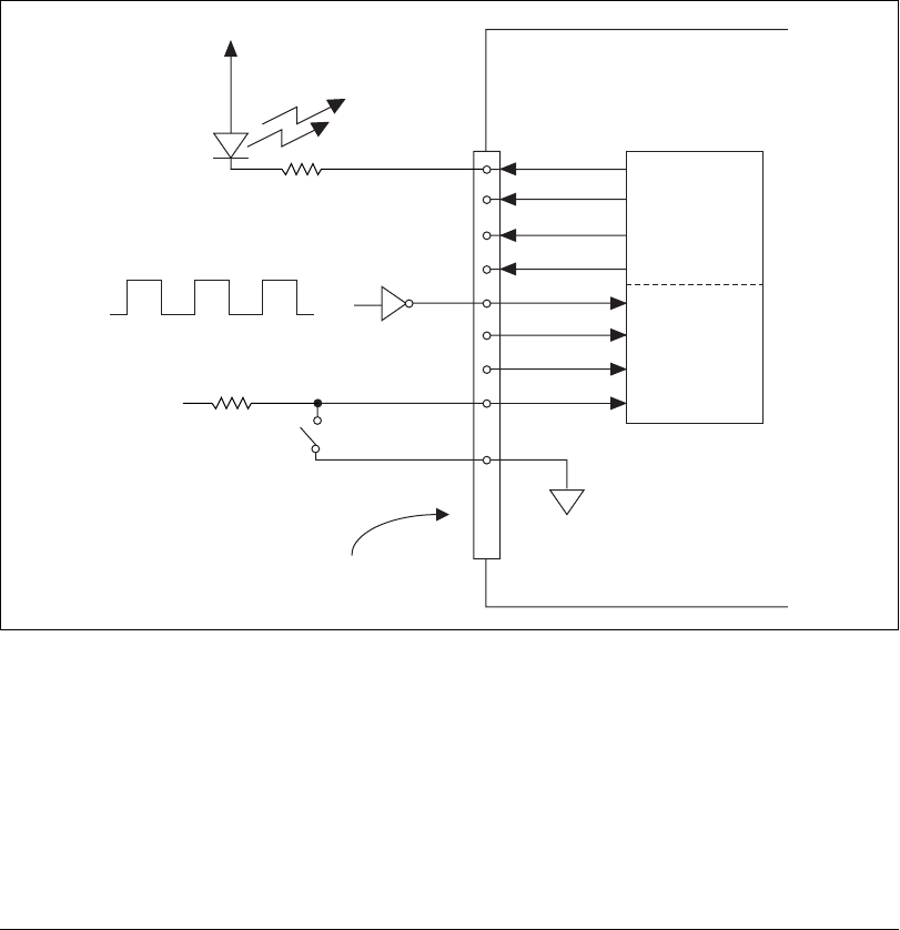
Figure 4-11 shows signal connections for three typical DIO applications.
Figure 4-11. DIO Connections
Figure 4-11 shows DIO<0..3> configured for digital input and DIO<4..7>
configured for digital output. Digital input applications include receiving
TTL signals and sensing external device states such as the state of the
switch shown in the figure. Digital output applications include sending
TTL signals and driving external devices such as the LED shown in the
figure.
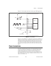
Power Connections
Two pins on the I/O connector supply +5 V from the PC power supply
using a self-resetting fuse. The fuse resets automatically within a few
seconds after the overcurrent condition is removed. These pins are
referenced to DGND and can be used to power external digital circuitry.
The combined total power rating for both pins should be between +4.65
VDC to +5.25 VDC at 1 A.
DIO<4..7>
DIO<0..3>
+5 V
LED
+5 V
TTL Signal
Switch
I/O Connector
DGND