


Chapter 3 Hardware Overview
AT E Series User Manual 3-6 ni.com
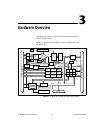
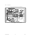
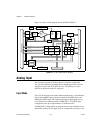
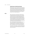
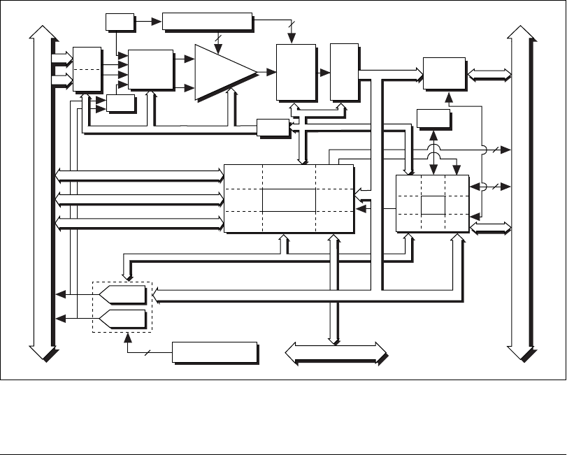
Figure 3-6 shows a block diagram for the AT-MIO-16XE-50.
Figure 3-6. AT-MIO-16XE-50 Block Diagram
Analog Input
The AI section of each AT E Series device is software configurable.
You can select different AI configurations through application software
designed to control the AT E Series devices. The following sections
describe in detail each of the AI categories.
Input Mode
The AT E Series devices have three different input modes—nonreferenced
single-ended (NRSE) input, referenced single-ended (RSE) input, and
differential (DIFF) input. The single-ended input configurations use up
to 16 channels (64 channels on the AT-MIO-64E-3). The DIFF input
configurationusesuptoeightchannels(32channelsonthe
AT-MIO-64E-3). Input modes are programmed on a per channel basis for
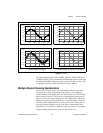
multimode scanning. For example, you can configure the circuitry to scan
Timing
PFI / Trigger
I/O Connector
3
2
RTSI Bus
AT –
I/O Channel
Digital I/O (8)
16-Bit
Sampling
A/D
Converter
EEPROM
Configuration
Memory
+
Programmable
Gain
Amplifier
–
Calibration
Mux
Mux Mode
Selection
Switches
Analog
Muxes
Voltage
REF
Calibration
DACs
4
Calibration
DACs
DAC0
DAC1
3
DAQ - STC
Analog Input
Timing/Control
Analog Output
Timing/Control
Digital I/O
Trigger
Counter/
Timing I/O
RTSI Bus
Interface
DMA/
Interrupt
Request
Bus
Interface
(8)
(8)
8
AI Control
Analog
Input
Control
EEPROM
Control
DMA
Interface
DAQ-PnP
DAQ-STC
Bus
Interface
Plug
and
Play
Analog
Output
Control
8255
DIO
Control
Bus
Interface
IRQ
DMA
Data
Transceivers
AO Control
ADC
FIFO
Data (16)
Data (16)