


Chapter 4 Connecting Signals
© National Instruments Corporation 4-13 AT E Series User Manual
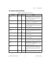
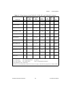
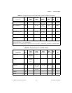
PFI6/WFTRIG DIO — V
cc
+0.5 3.5 at
(V
cc
–0.4)
5at0.4 1.5 50 kΩ pu
PFI7/STARTSCAN DIO — V
cc
+0.5 3.5 at
(V
cc
–0.4)
5at0.4 1.5 50 kΩ pu
PFI8/GPCTR0_SOURCE DIO — V
cc
+0.5 3.5 at
(V
cc
–0.4)
5at0.4 1.5 50 kΩ pu
PFI9/GPCTR0_GATE DIO — V
cc
+0.5 3.5 at
(V
cc
–0.4)
5at0.4 1.5 50 kΩ pu
GPCTR0_OUT DO — — 3.5 at
(V
cc
–0.4)
5at0.4 1.5 50 kΩ pu
FREQ_OUT DO — — 3.5 at
(V
cc
–0.4)
5at0.4 1.5 50 kΩ pu
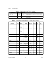
AI = Analog Input DIO = Digital Input/Output pu = pull up
AO = Analog Output DO = Digital Output
The tolerance onthe 50kΩ pull-up andpull-downresistors isvery large.Actual value mayrange between 17 kΩand 100 kΩ.
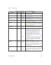
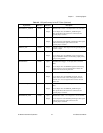
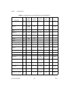
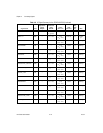
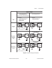
Table 4-6. I/O Signal Summary for the AT-MIO-16XE-50
Signal Name Drive
Impedance
Input/
Output
Protection
(Volts)
On/Off
Source
(mA at V)
Sink
(mA at V)
Rise
Time
(ns)
Bias
ACH<0..15> AI 20 GΩ in
parallelwith
100 pF
25/15 — — — ±3 nA
AISENSE AI 20 GΩ in
parallelwith
100 pF
25/15 — — — ±3 nA
AIGND AO — — — — — —
DAC0OUT AO 0.1 Ω Short-circuit
to ground
5at10 5at–10 2
V/µs
—
DAC1OUT AO 0.1 Ω Short-circuit
to ground
5at10 5at–10 2
V/µs
—
AOGND AO — — — — — —
DGND DO — — — — — —
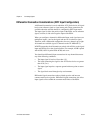
Table 4-5. I/O Signal Summary for the AT-MIO-16XE-10 and AT-AI-16XE-10 (Continued)
Signal Name Drive
Impedance
Input/
Output
Protection
(Volts)
On/Off
Source
(mA at V)
Sink
(mA at V)
Rise
Time
(ns)
Bias