


Chapter 4 Connecting Signals
AT E Series User Manual 4-38 ni.com
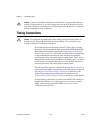
CONVERT* Signal
Any PFI pin can externally input the CONVERT* signal, which is
available as an output on the PFI2/CONVERT* pin.
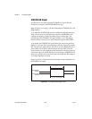
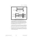
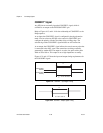
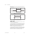
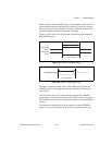
Refer to Figures 4-13 and 4-14 for the relationship of CONVERT* to the
DAQ sequence.
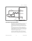
As an input, the CONVERT* signal is configured in the edge-detection
mode. You can select any PFI pin as the source for CONVERT* and
configure the polarity selection for either rising or falling edge. The
selected edge of the CONVERT* signal initiates an A/D conversion.
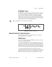
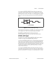
As an output, the CONVERT* signal reflects the actual convert pulse that
is connected to the ADC, even if the conversions are being externally
generated by another PFI. The output is an active low pulse with a pulse
width of 50 to 100 ns. This output is set to high-impedance at startup.
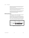
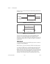
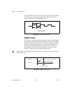
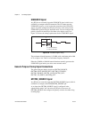
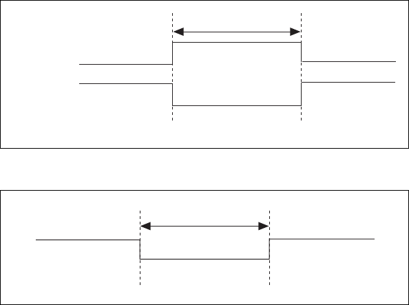
Figures 4-21 and 4-22 show the input and output timing requirements for
the CONVERT* signal.
Figure 4-21. CONVERT* Input Signal Timing
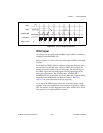
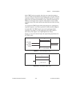
Figure 4-22. CONVERT* Output Signal Timing
Rising-Edge
Polarity
Falling-Edge
Polarity
t
w
= 10 ns minimum
t
w
t
w
=50to150ns
t
w