


Chapter 4 Connecting Signals
© National Instruments Corporation 4-43 AT E Series User Manual
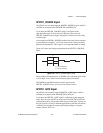
When using an external UPDATE signal, you must apply at least one more
external update pulse than the number of points that you want to generate.
This is necessary for proper hardware operation, otherwise the device does
not indicate that the waveform generation is complete.
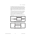
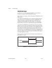
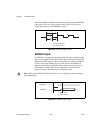
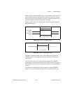
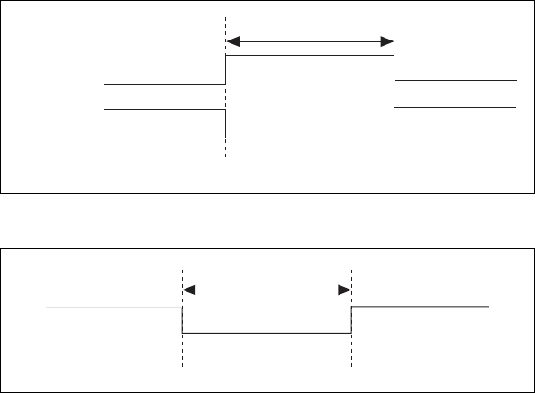
Figures 4-28 and 4-29 show the input and output timing requirements for
the UPDATE* signal.
Figure 4-28.
UPDATE* Input Signal Timing
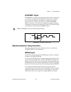
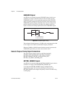
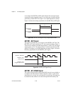
Figure 4-29. UPDATE* Output Signal Timing
The DACs are updated within 100 ns of the leading edge. Separate the
UPDATE* pulses with enough time that new data can be written to the
DAC latches.
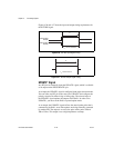
The AT E Series device UI counter normally generates the UPDATE*
signal unless you select some external source. The UI counter is started by
the WFTRIG signal and can be stopped by software or the internal Buffer
Counter.
D/A conversions generated by either an internal or external UPDATE*
signal do not occur when gated by the software command register gate.
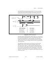
Rising-Edge
Polarity
Falling-Edge
Polarity
t
w
= 10 ns minimum
t
w
t
w
= 300 to 350 ns
t
w