


Chapter 4 Connecting Signals
© National Instruments Corporation 4-27 AT E Series User Manual
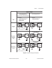
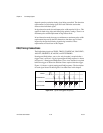
that (V
in
+) + (V
in
–) added to the gain times (V
in
+) – (V
in
–) must be within
±26 V of AIGND. At gains of 10 and 100, this is roughly equivalent to
restricting the two input voltages to within ±8 V of AIGND.
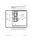
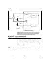
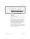
Analog Output Signal Connections
The AO signals are DAC0OUT, DAC1OUT, EXTREF, and AOGND.
Note
DAC0OUT and DAC1OUT are not available on the AT-AI-16XE-10. EXTREF is
not available on the AT-MIO-16XE-10, AT-AI-16XE-10, or AT-MIO-16XE-50.
DAC0OUT is the voltage output signal for AO channel 0. DAC1OUT is the
voltage output signal for AO channel 1.
EXTREF is the external reference input for both AO channels. You must
configure each AO channel individually for external reference selection in
order for the signal applied at the external reference input to be used by that
channel. If you do not specify an external reference, the channel uses the
internal reference.
Note
You cannot use an external AO reference with the AT-MIO-16XE-10,
AT-AI-16XE-10, or AT-MIO-16XE-50.
AO configuration options are explained in the Analog Output section of
Chapter 3, Hardware Overview.
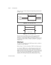
AOGND is the ground reference signal for both AO channels and the
external reference signal.
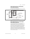
Figure 4-10 shows how to make AO connections and the external reference
input connection to the AT E Series device.